Introduction
What started as 'H-Mode mixer research' back in 2007, trying to squeeze the best out of this circuit, has now led to the design of a complete down-conversion HF receiver from scratch. The frontend has been completed already in 2008. This is now complemented with a "back-end" that matches its performance.
The following block diagram shows the architecture of the receiver. It is a conventional "single conversion superhet", down converting to a 9MHz IF with a high side local oscillator. Each subsystem in the signal path, starting with the Antenna Filters and ending with the Audio Amplifiers, has been designed with great care in order to minimize out-of-band, in-band and in-channel distortion the best as possible with common off the shelve modern components.
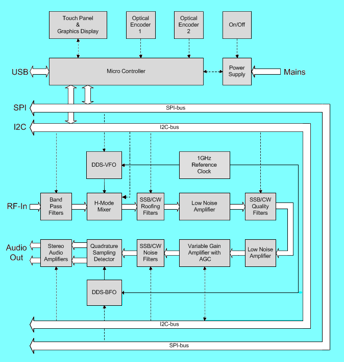
The block diagram shows that the receiver, although having a 100% analog signal path, is fully controlled over SPI and I2C serial busses by means of a central Micro-Controller. This allows for a flexible user interface utilizing a graphics display with integrated touch-panel, eliminating the need for most of the physical front panel controls except for 2 high resolution optical encoders and the inevitable On/Off pushbutton. Of course a CAT interface over USB is foreseen. The Micro-Controller subsystem however is not finished yet and its status is "experimental", but it will be completed in the near future.
Boards
The block diagram does not directly show the mapping of the various functional blocks to the physical boards. This mapping is given in the following list while navigating the signal path from the antenna to the speakers. The links provided point directly to the pages describing the boards, but most have top level pages discussing design choices one level up in the page hierarchy also!
Outside the signal path there are the DDS-VFO, DDS-BFO, 1GHz Reference Clock, Micro Controller and Power Supply. The Power Supply is finalized and documented in Switcher Board. The DDS's and Micro Controller are still work in progress and will be published when finished.
Gain Distribution
The performance of most functional blocks has been extensively quantified with regard to dynamic range with practical measurements. The key parameters are:
-
Noise Figure.
-
Gain.
-
3rd Order Input Intercept.
They are used to compute the following cumulative results when the functional blocks are cascaded in the signal path:
-
Cumulative Noise Figure, NF.
-
Cumulative Gain.
-
Cumulative 3rd Order Input Intercept, IIP3.
-
Minimum Discernible Signal, MDS.
-
3rd order limited Dynamic Range, IMD3DR.
The Gain Distribution Calculator presented below shows the measured parameters and calculates cumulative results. The Band selector sets the measured NF, Gain and IIP3 for the Antenna Filter and H-Mode Mixer. The Mode Selector sets the measured losses of the Roofing Filter, Quality Filter and Noise Filter. The bandwidth and Temperature fields are used in calculations where noise bandwidth is needed. All white input fields can be manually changed. Always type correct floating point values with a decimal point, because there is no input field error checking! To refresh the calculations, when manual changes have been applied to the input fields, press the Calculate button.
All presented IIP3 related data is with respect to out-of-band generated IMD. Therefore no values are listed in the stages that follow the Roofing Filter. The Roofing filter is the final stage that defines the out-of-band IMD performance. 20KHz 2-tone spacing is used. For close-in IMD performance of the frontend, have a look at the detailed measurements obtained for that subsystem. In-channel IP3 is entirely left out of this overview as it does not follow 3rd order law and can only be properly expressed in IMD dBc values.
The data clearly demonstrates that NF and MDS is mainly defined by the frontend. After the Quality Filter there is little degradation in MDS or NF. The NF of the QSD and the Audio stages have actually been "guessed" and are not measured values.
Comparing SSB mode with CW mode, the NF is 2.22dB worse. This is caused by the higher losses in the 500Hz Roofing Filter and the 500Hz Quality Filter. More gain in the LNA preceding the Quality Filter could have partially improved this. A much better solution is of course a CW Quality Filter with less insertion loss!
In the end, the obtained receiver NF and MDS for SSB and CW is such that we can speak of a very sensitive receiver without the application of a pre-amplifier before the mixer. This is one of the advantages of a down conversion architecture where two design principles that maximize dynamic range can be quite successful:
-
Keep losses as low as possible before any gain is applied.
-
Do not apply any gain before any roofing selectivity is applied.
Using these two principles it is entirely possible to obtain a NF of around 10dB without a pre-amplifier, which is sufficient most of the time on the HF bands even in a quiet location. That this result is also possible with an up-conversion frontend is shown elsewhere on this web-site with the data on the AR7070 receiver!
Sometimes there is confusion on how sensitivity is specified. On this web-site MDS in 2400Hz bandwidth at 290°K is used consistently unless otherwise specified. The bottom section of the Calculator gives the translation to other styles, which should help comparing with data from commercial equipment reviews. Especially the μV-style is not my favorite as it obscures the logarithmic nature of this property. Yet we see it used all the time, often in 500Hz bandwidth, while SSB is still the most common operating mode!
Please follow the links below to read more about the how and the why of the different receiver subsystems.
Frontend Subsystem
Local Oscillator Subsystem
IF Subsystem
Audio Subsystem
Power Supply Subsystem
Back to the TOC
|