|
Band-pass filters, first attempt
High dynamic range does not come easily. Without special attention, the band pass filters in front of the 1st mixer can easily bottleneck the IP3 of the frontend.
The first BPF unit that I build was not designed with low IMD in mind. I simply assumed that using T50 toroids instead of Toko tunable inductors would be enough to prevent IMD in the BPF's. I was wrong. This table shows the IIP3 at 0dBm and +6dBm input levels of those filters:
| Band Pass Filter |
| Band |
IIP3 (dBm) |
QL |
Core |
| 0dBm |
6dBm |
|
4x |
| 160 |
35,7 |
36,2 |
6,0 |
T50-2 |
| 80 |
38,2 |
39,5 |
5,3 |
T50-2 |
| 40 |
36,7 |
37,7 |
15,1 |
T50-6 |
| 30 |
35,5 |
36,5 |
26,7 |
T50-6 |
| 20 |
36,2 |
37,2 |
28,5 |
T50-6 |
| 17 |
36,6 |
41,3 |
23,8 |
T50-10 |
| 15 |
39,6 |
42,1 |
30,5 |
T50-10 |
| 12 |
39,3 |
40,8 |
28,8 |
T50-10 |
| 10 |
39,8 |
40,5 |
12,9 |
T50-10 |
The BPF's are 4-resonator capacitive top coupled (Cohn) filters designed to have the smallest bandwidth preferably with losses under -3dB. Therefore loaded Q is rather high on some bands. It is obvious that these BPF's need to be redesigned to fully exploit the IP3 performance of the H-Mode mixer.
One problem with the filters might be that they are build with cheap, mostly black NP0 ceramic capacitors, except on the lower 2 bands where the even worse violet variety had to be used.
The 4-resonator Cohn filters clearly represent an IP3 bottleneck given the performance obtainable with the H-Mode mixer.
Back to the drawing board, Toroids and IMD
After the disappointing results when I measured the initial BPF's, they were readied long before I could reliably measure IP3, it was clear that serious improvement was needed to have the BPF's not affect the frontends IP3 too much. On some bands like 40M, +50dBm IIP3 or better is needed!
Replacing the cheap ceramic junk by a better quality capacitor is an obvious easy to implement improvement. The decision was made to use polystyrene capacitors. Mica is probably OK too. I ruled out ATC-B chip capacitors as the relatively large pF values needed in some filters are not available. The new assumption from now on is that the capacitors are no more the cause of significant IMD when polystyrene or similar quality is used.
This leaves the inductors as the source of IMD. Air inductors are clearly IMD free, as copper and air is 'rather' linear. However the size of air coils to get high Q is problematic at least, not to mention the coupling between the coils. So unless the more manageable iron-powder core inductors are not good enough, the ultimate air coil solution will be on hold.
During discussions with Colin Horrabin, G3SBI, valuable insight came to how IMD is caused in iron powder toroids. It is all about the magnetic flux inside the core. For low flux values the core behaves fairly linear, but for higher flux values not. The flux inside the toroid core is determined by the following equation found in the Micrometals documentation:
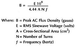
This simple formula reveals a number of ways to limit the flux inside the core:
-
The voltage over the inductor should be kept as low as possible. This means that the loaded Q of the filter should be kept low. Therefore the bandwidth of the BPF should be made as wide as is acceptable. There is obviously a trade off here. Too wide will allow more strong signals in the pass band adding to the voltage and hence the IMD. On the other hand wide filters have less insertion loss, improving the MDS figure and therefore also improving dynamic range. Given the superb linearity possible with the H-Mode mixer, the following statement is probably valid to some extent: "It will swallow anything you can throw at it...". Therefore the classic approach to make the BPF's as narrow as possible to fight the IMD is dropped partially. The classic approach is certainly correct in the NE602 days where the IP3 of a frontend was dominated by the mixer. So we make the BPF's wide enough to have very low insertion loss and have very little IMD generated inside the BPF itself and we just 'swallow' the extra signals that we let in. Given the optimum MDS attained with this approach extra pre-BPF attenuation can be applied to further improve the intercept point, band noise floor conditions permitting.
-
The number of turns should be as high as possible electrically and mechanically. This requires a relatively high inductance while still trying to maintain practical values for the capacitors. Note that inductance is proportional to N squared, so there are severe limitations in significantly increasing N.
-
In order to have more turns to lower the flux, the toroid should be made of material with low mu value. Usually the core material is selected based on the best possible Q in a resonant circuit. For IMD we may have to compromise the Q a bit and go for a lower mu material. Use yellow instead of red, use black instead of yellow and so on. By using bigger toroids at the same time, which improves the Q, the negative effect might be compensated. Furthermore when looking at a Flux versus Permeability graph in the Micrometals documentation the lower the mu of the material the more linear it becomes. -2, -7, -6, -10, -17 materials are increasingly linear in that order. -1, -15, -3, -8, -12 are increasingly 'wild' in that order.
-
The cross-sectional area of the toroid should be large. But larger cross-sectional area means less turns to maintain the same inductance, unless the path length of the magnetic field is increased with the same factor. So simply stacking toroids to increase A does not decrease IMD. Bigger toroids with a larger diameter are needed.
-
The flux is reverse proportional with the working frequency of the filter. More difficulty to maintain good IP3 can be expected at the lower bands. It looks like we will have to work harder to obtain low IMD on 160M than we have to on 20M.
The above points will be used to improve the OIP3 of each BPF up to the point that it does not too much hurt the IIP3 of the frontend without the BPF, if possible.
The most dramatic way to lower the Q and increase the bandwidth of the BPF's is to use just low-pass filters in combination with a very good notch to filter out the IF frequency. My LO is always on the high-side. This would be "It will swallow anything you can throw at it..." to the extreme. I think it is too extreme and will open up the frontend much more to IMD2 also. To a lesser extent the same holds for half-octave BPF's.
Band-pass filters, second attempt
A practical solution providing a good balance between different conflicting forces such as intercept point, insertion loss, stop band performance and selectivity has been found in a passive motherboard that forms the ground plane that has up to a maximum of 12 different BPF boards plugged in for each amateur band from 160M to 6M plus 2 spares. Also a sharp IF notch filter and a precise step attenuator are provided as plug-in boards.
The following links point to the different boards used in the BPF subsystem:
-
Mother board
-
I2C controller board
-
Attenuator board
-
Band pass filter board(s)
-
9MHz IF notch board
Specification
The following table summarizes the key parameters of the finalized Band Pass Filter Box:
| Bandpass Filter Box Specs |
| Dimensions |
250 x 160 x 60 |
mm |
| Weight |
1.72 |
Kg |
| Supply Voltage |
+13.5 to +15 |
V |
| Supply Current |
55 - 100 |
mA |
| Input Impedance |
50 |
Ω |
| Output Impedance |
50 |
Ω |
| Notch Frequency |
9 |
MHz |
| Notch Depth |
80 |
dB |
| Attenuator Range |
0 - 30 |
dB |
| Attenuator Step Size |
2 |
dB |
| 160M BPF |
| Insertion Loss |
0.64 |
dB |
| Center Frequency |
1.900 |
MHz |
| -3dB Band Width |
0.403 |
MHz |
| 20KHz separated IIP3 of BPF |
+46.7 |
dBm |
| Image Rejection |
93 |
dB |
| 9MHz IF Rejection |
119 |
dB |
| 80M BPF |
| Insertion Loss |
0.56 |
dB |
| Center Frequency |
3.750 |
MHz |
| -3dB Band Width |
0.836 |
MHz |
| 20KHz separated IIP3 of BPF |
+50 |
dBm |
| Image Rejection |
105 |
dB |
| 9MHz IF Rejection |
117 |
dB |
| 40M BPF |
| Insertion Loss |
1.20 |
dB |
| Center Frequency |
7.200 |
MHz |
| -3dB Band Width |
0.774 |
MHz |
| 20KHz separated IIP3 of BPF |
+50.5 |
dBm |
| Image Rejection |
105 |
dB |
| 9MHz IF Rejection |
120 |
dB |
| 30M BPF |
| Insertion Loss |
1.60 |
dB |
| Center Frequency |
10.250 |
MHz |
| -3dB Band Width |
0.943 |
MHz |
| 20KHz separated IIP3 of BPF |
+48.6 |
dBm |
| Image Rejection |
104 |
dB |
| 9MHz IF Rejection |
107 |
dB |
| 20M BPF |
| Insertion Loss |
1.40 |
dB |
| Center Frequency |
14.150 |
MHz |
| -3dB Band Width |
1.425 |
MHz |
| 20KHz separated IIP3 of BPF |
+49.8 |
dBm |
| Image Rejection |
103 |
dB |
| 9MHz IF Rejection |
110 |
dB |
| 17M BPF |
| Insertion Loss |
1.48 |
dB |
| Center Frequency |
18.000 |
MHz |
| -3dB Band Width |
1.856 |
MHz |
| 20KHz separated IIP3 of BPF |
+49.3 |
dBm |
| Image Rejection |
113 |
dB |
| 9MHz IF Rejection |
116 |
dB |
| 15M BPF |
| Insertion Loss |
1.44 |
dB |
| Center Frequency |
21.250 |
MHz |
| -3dB Band Width |
2.395 |
MHz |
| 20KHz separated IIP3 of BPF |
+47.1 |
dBm |
| Image Rejection |
111 |
dB |
| 9MHz IF Rejection |
102 |
dB |
| 12M BPF |
| Insertion Loss |
1.60 |
dB |
| Center Frequency |
24.750 |
MHz |
| -3dB Band Width |
2.681 |
MHz |
| 20KHz separated IIP3 of BPF |
+45.7 |
dBm |
| Image Rejection |
102 |
dB |
| 9MHz IF Rejection |
100 |
dB |
| 10M BPF |
| Insertion Loss |
1.80 |
dB |
| Center Frequency |
29.000 |
MHz |
| -3dB Band Width |
3.056 |
MHz |
| 20KHz separated IIP3 of BPF |
+44.2 |
dBm |
| Image Rejection |
109 |
dB |
| 9MHz IF Rejection |
100 |
dB |
| 6M BPF |
| Insertion Loss |
3.36 |
dB |
| Center Frequency |
51.500 |
MHz |
| -3dB Band Width |
4.390 |
MHz |
| 20KHz separated IIP3 of BPF |
+44.6 |
dBm |
| Image Rejection |
72 |
dB |
| 9MHz IF Rejection |
102 |
dB |
Note that the above presented results are obtained with polystyrene capacitors for all bands. The superior ATC100-B chip capacitors give quite similar results on most bands. However practical results on 6M are noticeable better with ATC100-B and are close to the simulated results with lower insertion loss, wider bandwidth and better image rejection without parasitic pole on the low side of the filter! ATC100-B capacitors are supported in the Rev-B PCB layout now also available for homebrew PCB production.
Back to Frondend Introduction
Back to the TOC
|