40M Band Pass Filter
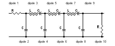
Series-Trap, Shunt-C filter topology is used. Just 3 sections are enough to obtain more than sufficient image rejection. The filter design is based on a 0.1dB ripple Chebyshev response. The schematic is shown in the following drawing:
Because of design constraints, especially regarding IMD, the following theoretical and practical component values are chosen:
| 40M BPF, Fc=7200KHz, BW=774KHz, Ql=9.3 |
| Dipole |
Design |
Implementation |
Inductor |
| R (ohm) |
L (uH) |
C (pF) |
R (ohm) |
L (uH) |
C (pF) |
C (pF) ATC |
Core |
# turns |
wire (mm) |
| 1 |
50 |
|
|
50 |
|
|
|
|
|
|
| 2 |
|
|
317 |
|
|
270 |
270 |
|
|
|
| 3 |
|
9.50 |
59 |
|
8.50 |
33 + 27 |
62 |
T94-10 |
38 |
0.65 |
| 4 |
|
|
702 |
|
|
680 + 22 |
680 + 22 |
|
|
|
| 5 |
|
9.50 |
60 |
|
8.50 |
33 + 27 |
62 |
T94-10 |
38 |
0.65 |
| 6 |
|
|
702 |
|
|
680 + 22 |
680 + 22 |
|
|
|
| 7 |
|
9.50 |
59 |
|
8.50 |
33 + 27 |
62 |
T94-10 |
38 |
0.65 |
| 8 |
|
|
317 |
|
|
270 |
270 |
|
|
|
| 10 |
50 |
|
|
50 |
|
|
|
|
|
|
Dipole 1 and 10 represent the filters input and output impedance in the simulation and are not physically present in the real circuit. The practical capacitors are made up from combinations of standard values. The first column shows the values I used with Polystyrene capacitors. The other column shows values when ATC100-B chip capacitors are used. The inductors are fine tuned by changing the distribution of turns around the toroid.
Dipole 2 and 8, that match the filter to 50 ohms, have been reduced by about 50pF in order to compensate for the parasitic capacitance of the complete motherboard system.
In simulation when the coils are modeled with a Q=200 the filter has the following key characteristics:
-
Insertion loss: 1.0dB
-
Image rejection at 25MHz: 126dB (!)
-
IF rejection at 9MHz: 46dB
-
-3dB bandwidth: 800KHz
-
Center frequency: 7150KHz
The 126dB image rejection at 25MHz is theoretical and will probably not be realized in real life. The IF rejection at 9MHz is really insufficient by itself. However the H-Mode mixer's symmetry will add an additional 55dB of attenuation, bringing the IF rejection at 100dB. The objective is 120dB or more, so the notch filter at 9MHz will have to give the missing 20dB or more.
IMD comparison: toroids, toroids...
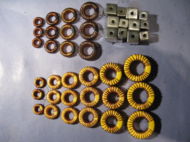
Because of the challenging +50dBm IMD requirement and also out of curiosity a fairly wide range of Micrometals toroids have been tested and also a couple of Lodestone Pacific shielded coil formers. All the resulting inductors have been tested with the same filter assembly utilizing Suflex 2.5% polystyrene capacitors. The following picture shows the bunch that has been put to the test:
The table below summarizes the measurement data. The 2-tones have 20KHz separation. IMD is measured at 0dBm and 5dBm input levels to detect non 3rd order law behavior. MDS is measured within 2.2KHz bandwidth:
| 40M BPF IMD comparison, FSA3157 + T1-6T mixer, QT roofing filter |
| Core |
|
IIP3 2-tone level 0dBm |
IIP3 2-tone level 5dBm |
| IL |
MDS |
BPF |
-BPF |
+BPF |
IMD3DR |
BPF |
-BPF |
+BPF |
IMD3DR |
| (-dB) |
(-dB) |
(dBm) |
(dBm) |
(dBm) |
(dB) |
(dBm) |
(dBm) |
(dBm) |
(dB) |
| T130-6 |
1.44 |
132.0 |
52.4 |
51.7 |
51.4 |
122.3 |
54.7 |
51.2 |
53.4 |
123.6 |
| T106-6 |
0.80 |
132.5 |
52.4 |
51.7 |
51.2 |
122.4 |
55.4 |
51.2 |
55.2 |
125.1 |
| T94-6 |
0.72 |
132.5 |
51.4 |
51.7 |
50.4 |
121.9 |
53.9 |
51.2 |
53.4 |
123.9 |
| T80-6 |
0.80 |
132.5 |
48.2 |
51.7 |
47.7 |
120.1 |
49.9 |
51.2 |
48.9 |
120.9 |
| T68-6 |
0.96 |
132.5 |
41.7 |
51.7 |
41.2 |
115.8 |
42.7 |
51.2 |
42.7 |
116.8 |
| T50-6 |
1.04 |
132.5 |
42.4 |
51.7 |
42.4 |
116.6 |
45.2 |
51.2 |
45.2 |
118.4 |
| T94-10 |
1.20 |
132.5 |
50.6 |
52.3 |
50.1 |
121.7 |
52.6 |
52.3 |
51.1 |
122.4 |
| T80-10 |
0.80 |
132.5 |
48.2 |
51.7 |
47.7 |
120.1 |
50.2 |
51.2 |
49.2 |
121.1 |
| T68-10 |
0.88 |
132.5 |
46.2 |
51.7 |
45.4 |
118.6 |
47.9 |
51.2 |
47.9 |
120.3 |
| T50-10 |
0.96 |
132.5 |
43.9 |
51.7 |
43.9 |
117.6 |
46.4 |
51.2 |
46.4 |
119.3 |
| L57-6 |
2.16 |
131.5 |
42.4 |
51.7 |
42.4 |
115.9 |
45.4 |
51.2 |
45.4 |
117.9 |
| L45-6 |
2.08 |
131.5 |
42.4 |
51.7 |
42.4 |
115.9 |
45.4 |
51.2 |
45.4 |
117.9 |
| L57-10 |
2.12 |
131.5 |
46.9 |
51.7 |
45.9 |
118.3 |
47.9 |
51.2 |
47.9 |
119.6 |
| L45-10 |
2.12 |
131.5 |
46.4 |
51.7 |
45.4 |
117.9 |
47.9 |
51.2 |
47.7 |
119.4 |
The table requires some explanation. For each core the insertion loss of the resulting BPF and the MDS figure for the complete frontend with that BPF is given. Next IMD results at 0dBm input tones and 5 dBm input tones are given. The columns marked 'BPF' show the IIP3 of the BPF only. The columns marked '-BPF' show the IIP3 of the frontend without the BPF in front and the columns marked '+BPF' show the IIP3 of the complete frontend including the BPF. Also the IMD3 dynamic range is computed and shown.
A number of additional remarks to the measurements:
-
All measurements are done with the filters stand-alone, without the 2 switching relays. This also means without the complete BPF motherboard and its additional circuitry like the notch filter and the attenuator board. So the IL and MDS figures do NOT include the small but measurable additional losses (about 0.2dB) introduced by the attenuator board (4 relays), the 9MHz notch and the 2 relays on the measured BPF board. The only exception is the T94-10 filter (cyan). This filter is measured with the overhead of the total BPF box assembly!
-
Really all tested coil formers give good results on 40M. A dynamic range better than 116dB is always impressive! It is a pity however that I did not have Toko pre-wound shielded coils at my disposal to do a baseline measurement with.
-
Bigger toroids mean less IMD. T94 or bigger is needed to get above +50dBm. This is matching our expectations with regard to the toroids flux.
-
Bigger toroids mean better Q and less IL, although the tipping point seems to be the T106 and certainly the T130 cores.
-
For a given size, the black material is almost always better and sometimes significantly better than the yellow material with regard to IMD.
-
The black material does not introduce significant extra losses on 7MHz, where usually yellow toroids are utilized.
-
Even the biggest iron powder cores produce IMD not strictly following 3rd order law. This is bad news, but the only alternative seems to be to use humongous air coils with all mechanical and electrical difficulties they will introduce... Back to the era of the HRO?
-
T68-6 performs less with IMD than T50-6 in this test. This is odd and might be caused by a bad set of toroids. Likewise I have seen a set of T94-6 toroids obtained from a different but imho reliable distributor produce double the insertion loss than the ones tested in this table.
-
With regard to IMD there is no improvement with the bigger L57 formers over the L45's. The explanation could be that the L57 and L45 use identical sized tunable inner cores, which will obviously saturate at similar flux levels, giving the L57 only a potential advantage with the obtainable Q.
-
With regard to IL, Q the L57 is not much better than the smaller L45. The Lodestone formers don't reach the high-Q that is obtained with the toroids in this test. It proves difficult to produce a high-Q 9.5uH coil with those formers at 7MHz. In order to have a high-Q on 7MHz only a single layer of turns should be used to reduce parasitic capacitance. A single layer requires the use of 0.13mm or thinner wire to fit the amount of turns needed in the small space available. I have only 0.1mm at my disposal. The resistance and the skin effect with this small wire size is limiting the Q noticeably. Less turns (less inductance...), and therefore thicker wire will be better for the Q, but not for IMD where many turns are needed to reduce the flux.
One point worth noting here is that especially with the big toroids the IIP3 of the filter is close to the limit of the measurement system. The BPF's will never exactly match 50 ohms in the pass band. Therefore the isolation that the hybrid combiner gives will be deteriorated, increasing the built-in IMD of the 2-tones. This could be the reason why the humongous T130-6 does only marginally better than the T94-6 in this test.
40M BPF with T94-10
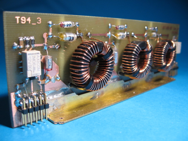
Six of the bigger type 6 and type 10 cores in this test do break the magic 120dB IMD3DR boundary in SSB bandwidth. My favorite however is the BPF build-up with the T94-10, marked with cyan in the table. It is the 'smallest' core that produces the right combination of low IL and high IIP3 to give the best IMD3DR of the complete frontend. A picture of the assembled filter PCB is shown below. It measures 160x50mm, a half height eurocard. The assembly is meant to be plugged onto a motherboard with 9 other similar BPF's and a 9MHz notch filter board:
The winning T94-10 40M filter is exposed to a more detailed IMD measurement when hooked up to the mixer. The table shows the IMD at a fixed input level of +0,4dBm at various 2-tone offsets for the complete frontend:
| IMD of T94-10 40M BPF, FSA3157 + T1-6T mixer, QT roofing filter at 0.4dBm input level |
| 2-tone offset (KHz) |
IMD 1 (-dBc) |
IMD 2 (-dBc) |
IIP3 1 (dBm) |
IIP3 2 (dBm) |
IIP3 avg (dBm) |
| 100 |
101 |
102 |
50.9 |
51.4 |
51.2 |
| 50 |
101 |
102 |
50.9 |
51.4 |
51.2 |
| 20 |
101 |
102 |
50.9 |
51.4 |
51.2 |
| 10 |
101 |
102 |
50.9 |
51.4 |
51.2 |
| 5 |
97 |
100 |
48.9 |
50.4 |
49.7 |
| 2 |
92 |
90 |
46.4 |
45.4 |
45.9 |
| 1 |
87 |
85 |
43.9 |
42.9 |
43.4 |
| 0.5 |
78.8 |
80.8 |
39.8 |
40.8 |
40.3 |
Outside the pass band of the roofing filter, the frontend's IIP3 quickly reaches slightly over +50dBm. At 2KHz separation the IMD3DR is already 119dB.
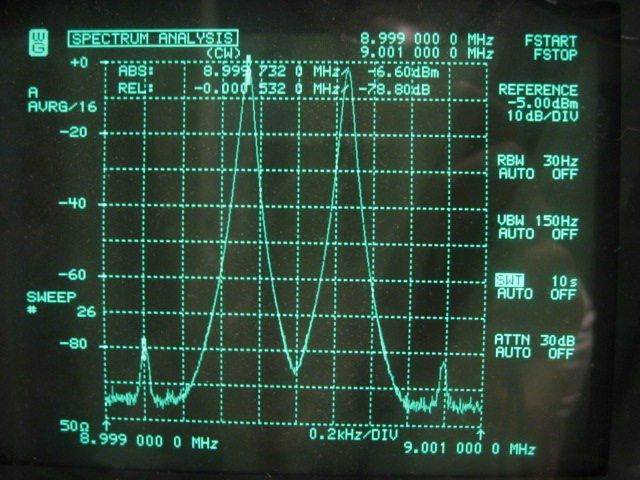
At 500Hz separation the IMD measurement is completely within the SSB bandwidth of the roofing filter. Therefore the lower in band IP3 of the roofing filter dominates the overall figure in that case. Given the results of the roofing filter alone (+38.9dBm) a higher value is expected with the mixer and the BPF in front. Maybe the in band IMD is not quite following 3rd order law. The following spectrum analyzer picture shows the in-band 500Hz IMD measurement:
Measurement overview
The following table summarizes some measurements made to the T94-10 40M BPF:
| 40M BPF results, FSA3157 + T1-6T mixer, QT roofing filter |
| BPF Filter Center |
7200 |
KHz |
| BPF -3dB Band Width |
774 |
KHz |
| BPF Loaded Q |
9.3 |
|
| BPF Insertion loss |
-1.20 |
dB |
| MDS level without BPF |
-134 |
dBm |
| MDS level with BPF |
-132.5 |
dBm |
| IP3 frontend without BPF @ 0dBm |
+52.3 |
dBm |
| IP3 of BPF only @ 0dBm |
+50.5 |
dBm |
| IP3 of frontend with BPF @ 0dBm |
+50.1 |
dBm |
| IMD3 dynamic range @ 0dBm |
121.7 |
dB |
| Image rejection @ 25MHz |
-105 |
dB |
| BPF box IF rejection @ 9MHz @ 0dBm |
-120 |
dB |
Single tone spurious responses
The following table shows the relevant single tone spurious responses of the H-Mode mixer frontend with the 40M BPF. Spurious signals are determined by the following equation: | n * Fo � m * Fs | = Fif, where n = 0, 1, 2, 3, 4, 5 and m = 1, 2, 3, 4, 5. The number of possible spurs up to 5'th order is 55, but only those that fall within the -40dB pass band of the BPF are investigated. Higher order spurs and spurs outside the -40dB pass band are considered insignificant and have not been measured. The spur test signal is a very strong 0dBm (S9+73dB!) signal.
| 40M BPF + frontend single-tone spurious responses at 7.200.000Hz, @ 0dBm input level |
| Description |
Order: (n,m) |
F-spur (Hz) |
level (dBm) |
| IF |
(0,1) |
9.000.000 |
< -127 |
| Image |
(1,1) |
25.200.000 |
-105 |
|
(1,3) |
8.400.000 |
< -127 |
|
(1,4) |
6.300.000 |
-125 |
|
(2,3) |
7.800.000 |
< -125 |
|
(2,4) |
5.850.000 |
-126 |
|
(2,5) |
8.280.000 |
< -127 |
|
(3,5) |
7.920.000 |
< -126 |
The cyan colored measurements are limited due to the phase noise levels of the signal generator and / or LO. The given values are the best that could be done.
Transmission
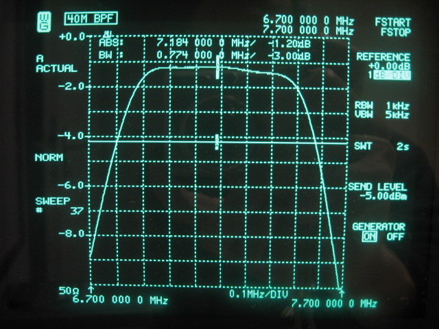
The next analyzer plot shows the pass band characteristics of the T94-10 40M filter. IL is around 1.20dB over the entire 40M band at a -3dB bandwidth of 774KHz. It can be observed that the 9MHz notch filter is slightly 'pulling' at the right side of the filter curve:
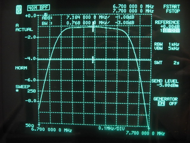
The next analyzer plot again shows the pass band characteristics of the T94-10 40M filter, but this time without the 9MHz notch filter in place. IL is around 1.08dB over the entire 40M band at a -3dB bandwidth of 768KHz. The negative impact of the notch is -0.12dB, which matches exactly the separate measurements on the notch filter! The value of the IL indicates that the Q's of the inductors are close to about 200:
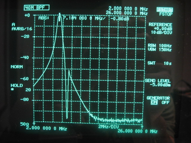
The following analyzer plot shows the wideband insertion loss up to the image frequency at 25MHz. At 9MHz the attenuation is about the predicted 45dB. The drastic dip of the notch filter is clearly visible. The stop band is close to the analyzers available 100dB range.
The 9MHz IF rejection is measured at < -130dB (not measurable), with the 9MHz notch in place. The image rejection is measured at -105dB.
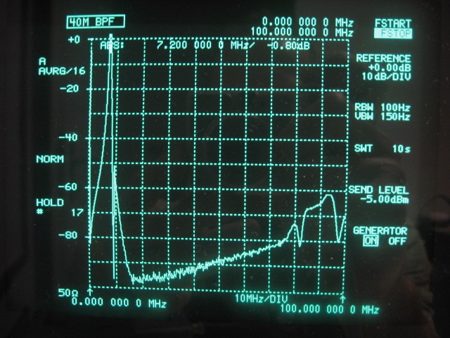
The following analyzer picture is a wideband plot up to 100MHz. Stop band reduces abruptly beyond 80MHz. Probable causes are self resonance of the big toroid inductors and / or resonance of the entire filter slot as a cavity resonator. With a pure enough LO signal this reduced stop band performance at those frequencies should not be of much concern.
Reflection
Finally the impedance of the filter is measured with N2PK-VNA and Exiter software:
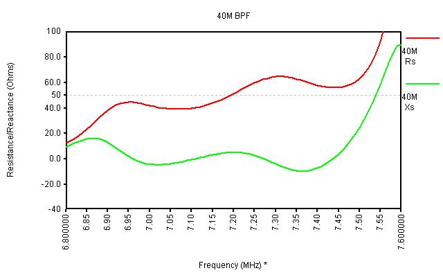
The measured curve almost overlaps the curve when simulating the theoretical filter and shows a good match to a 50 ohm system. The real filter behaves much like the simulated version. The biggest difference is the bandwidth. Probably due to the parasitic capacitance of the big toroid inductors the real bandwidth came out at around 760KHz rather than the simulated 800kHz.
The T94-10 40M filter has met all the requirements except for complete 3rd order linearity. It enables the full potential of the FSA3157 H-Mode mixer and the subsequent roofing filter. And this is a great advantage on the 40M band where strong signals are at their very strongest.
In case IMD remains a problem on this band with this relatively wide filter, allowing many broadcast stations inside the pass band, not all is lost and there are the following options:
-
Atmospheric, man-made and galactic noise levels on 40M will often allow for some attenuation. At an SSB MDS of -133dBm, an additional -10dB between the antenna and the frontend will bring the IP3 above +60dBm, while still maintaining reasonable sensitivity. For this reason the attenuator board has been added, that will allow up to 30dB of attenuation in 2dB steps. It will be possible to set the NF of the frontend to match the real life noise floor in order to get the best dynamic range possible.
-
A selective high-Q air coil based pre-selector between the antenna and the frontend might be used to filter out the 100KHz portion of interest.
PCB artwork and schematic for the 3-pole filter board in PDF format.
160M BPF
80M BPF
30M BPF
20M BPF
17M BPF
15M BPF
12M BPF
10M BPF
6M BPF
Back to BPF Boards
Back to the TOC
|