Attenuator Board
Depending on the band and the external conditions (man made noise, atmospheric noise and galactic noise) the sensitivity of the frontend can be way too good! An MDS of -133dBm is not very useful when the band conditions are such that for instance the external noise floor is found at S5 level, some 30dB higher! Raising the noise floor of the frontend to be just a bit below the external noise floor will guarantee the best possible strong signal handling capability.
For this reason a step attenuator is implemented that can be adjusted in sixteen 2dB steps from 0dB to 30dB. This must be adequate for most conditions. The IIP3 of the frontend will be around +80dBm when the attenuator is set at 30dB!
To have the best result, the attenuator board is the first board in the RF chain. It will reduce IMD in any subsequent stages of the frontend and hopefully the resistors and relays of the attenuator are completely without IMD themselves...
The following picture shows the resulting 1/2 height eurocard plug-in board:
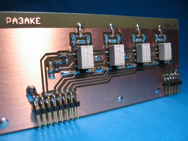
The circuit is straight forward and consists of 4 quality SMD signal relays switching in respectively 2dB, 4dB, 8dB and 16dB attenuation made of 1% 1206 resistors. The relay contacts are DC-wetted to prevent deterioration of the gold plated relay contacts. The PCB is double-sided with the back side only acting as a full ground plane.
At this moment my firmware does not yet support activating the 4 attenuator sections through I2C. Therefore I can not yet show any data on the attenuators accuracy when used on the HF bands. When I have the data available I will present it here!
PCB artwork and schematic for the BPF attenuator board in PDF format.
Mother Board
I2C Controller Board
Band Pass Filter Board(s)
IF Notch Board
Back to Frondend Input Band Pass Filters
Back to the TOC
|