Quartz Filter Switching
The INRAD filters showed peak in-band IIP3 at around +30dBm for the 2400Hz SSB filter and +19dBm for the 500Hz CW filter. We cannot improve the internals of these filters, so our design goal is to not further degrade the in-band IMD performance by the other circuits on the selectivity board. Therefore the SPDT switches should have significant less IMD than the quartz filters they are switching. So we are looking for a switch solution with > +30dBm, preferably > +36dBm intercept.
Using signal relays, as is done on the frontend board to switch the roofing filters, will be a quality solution contributing to no extra IMD at all. However protected behind the roofing filter and in comparison to the +30dBm in-band intercept of the SSB quartz filter our IMD constraints are not quite as severe as in the frontend and we can consider a less expensive and also physically smaller solution. The SPDT bus switches used so successfully in the H-Mode mixer double balanced switching application are a good candidate to also switch the quartz filters. They are really small and consume almost no power. We have to investigate what the penalty is of using FSA3157 in this application compared to signal relays.
FSA3157 SPDT Switches
For testing FSA3157 as a switch in the signal path to switch the quartz filters the following test circuit has been used:
The switches are biased at Vdd/2 and the quartz filter has been replaced by a track. Care has been taken to provide good isolation between input and output, both in control lines and power supply lines. With this test circuit on a small PCB, the FSA3157 has been tested for the important parameters as a signal switch:
-
Insertion Loss
-
Isolation
-
IMD
Switch ON: Insertion Loss
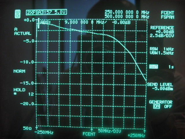
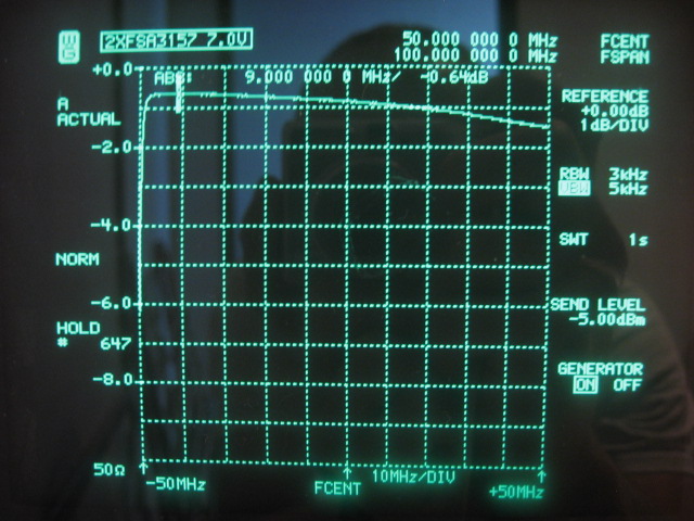
From the FSA3157 datasheet it becomes clear that the Ron of the switch is depending on supply voltage Vdd and also on the current through the switch. The latter is not important in this small signal application! The following picture shows the insertion loss of the pair of FSA3157 under test over a 500MHz wide span centered at 250MHz at nominal supply voltage of 5V. The -3dB bandwidth is a whopping 300MHz and the first 50MHz show real low IL, which is perfect for our 9MHz IF application!
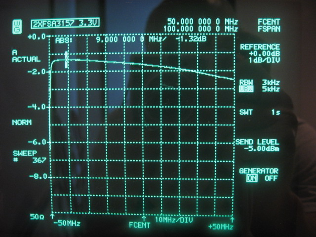
The following picture shows the first 100MHz of the IL. Vdd is 3.3V. At 9MHz we have 1.32dB insertion loss.
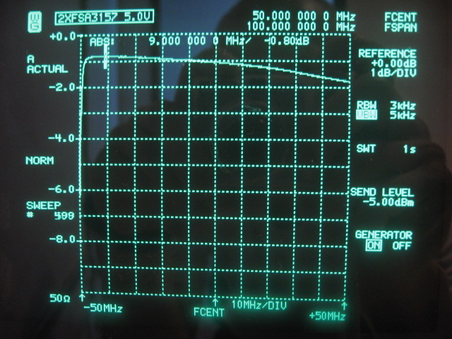
The following picture shows the first 100MHz of the IL. Vdd is 5V. At 9MHz we have 0.80dB insertion loss.
The following picture shows the first 100MHz of the IL. Vdd is 7V. At 9MHz we have 0.64dB insertion loss. 7V is the absolute maximum supply voltage for the FSA3157 according to the manufacturer. On the frontends board H-Mode mixer, Vdd is 6.8V and there are no reliability problems showing up in practice.
The above pictures show a decreasing trend in Ron with increasing Vdd. From this the effective small signal RF Ron can be calculated. This is per switch approximately 7.5Ω at 3.3V Vdd, 5Ω at 5.0V Vdd and 3.75Ω at 7.0V Vdd.
The insertion loss of 0.64dB at Vdd is 7V is small compared to the insertion loss of the filter being switched. The extra loss can be tolerated as the preceding LNA on the selectivity board has enough headroom to compensate for it. From an IL point of view, the FSA3157 switches are suitable to switch the crystal filters!
Switch OFF: Isolation
When switched off, the obtainable isolation is important. Preferably the isolation provided by the bus switches should be in the same order of magnitude as the stop band isolation of the quartz filters. The following network analyzer plot shows the isolation from DC to 500MHz:
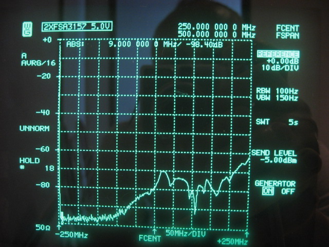
For the first 120MHz, the isolation is close to -100dB, slowly climbing towards -70dB at the -3dB point of the pair of switches. This is better than the practically obtainable stop-band of the quartz filters. There are no surprises when we zoom in to the first 100MHz:
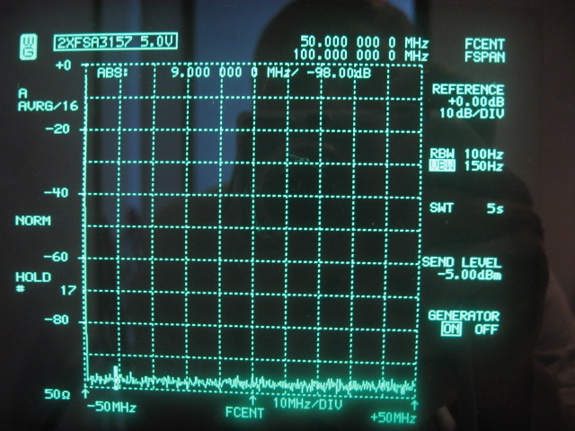
Given that the measured isolation is at the end of the 100dB range of the analyzer, there is probably a bit more in there than shown on the picture. This result makes FSA3157 100% suitable for switching the filters with respect to the OFF isolation!
Switch ON: IMD
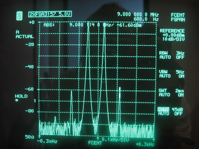
The last thing to investigate is the IMD performance obtainable with the bus switches. Our design goal is a +36dBm or better 3rd order intercept. The following picture shows 80Hz spaced 2-tones, IMD3 and IMD5 around 9MHz with Vdd is 3.3V. This is the worst case scenario. The 3rd order output intercept is +25.8dBm. Remarkable is the strong level of the 5th order IMD being equal to the level of 3rd order IMD!
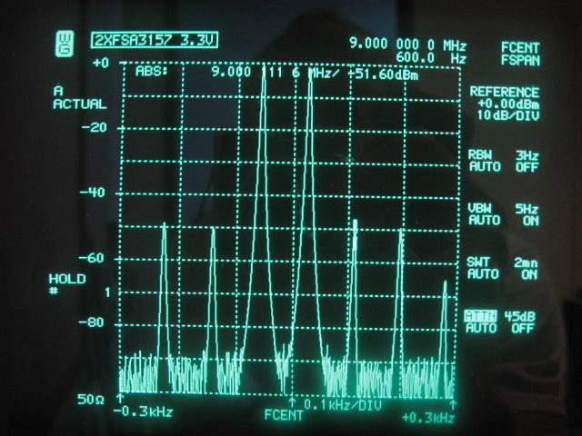
The following picture shows 80Hz spaced 2-tones and IMD3 around 9MHz with Vdd is 5.0V. The 3rd order output improves to +30.8dBm. That is a significant improvement. The 5th order IMD has about completely vanished.
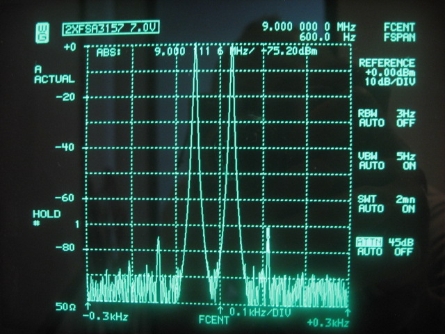
The following picture shows 80Hz spaced 2-tones and IMD3 around 9MHz with Vdd is 7.0V. The output intercept improves to +37.6dBm. Again this is a significant improvement. It proves again that FSA3157 should get the highest allowable Vdd for best IMD performance.
The OIP3 of +37.6dBm at Vdd is 7V fulfills our requirement regarding IMD. At 7V the bus switches will not contribute much to the in-band IMD3 of the selectivity board. This result is so good that no experiments have been done at different bias voltages other than Vdd/2. Given the results obtained with testing the H-Mode mixers, probably a slightly lower bias voltage may give further improvement.
Conclusion
Insertion loss, loss of isolation and IMD3 contributed by the FSA3157 bus switches do not compromise the performance of the selectivity board, given the performance obtainable with the commercial quartz filters. Therefore the FSA3157 SPDT bus switch makes a good, compact and affordable solution. Given that all three measured aspects are quite sufficient, no further effort is invested in other SPDT bus switch candidates. Several pin-compatible parts exist with even lower Ron such as FSA4157 and FSA5157, but with much slower switching times. (Not important in this application, but useless for H-Mode mixers!). The effort to look at those does not seem justified given the results obtained with FSA3157.
FSA3157 in its SC70 package is very small. In practice it takes a bit more board area to implement analog signal switching as it requires extra components for the DC voltage biasing. Signal relays are much larger and do require extra components as well for DC current wetting. Other advantages of using FSA3157 over signal relays are:
-
Completely silent when switching.
-
Very low power consumption.
-
Very fast switching.
When ordering FSA3157's for use in H-Mode mixer's, order a bunch more for doing signal switching behind the roofing filters as well! At 0.25€ each in quantities of 25 this is a very affordable solution compared to the much more expensive signal relays.
Given the +37.6dBm IP3 figure and relative low insertion loss of -0.64dB, some may consider using the FSA3157 to switch the band-pass filters and attenuators in the BPF box when highest possible dynamic range of the frontend is not needed. One can think of a smaller version of the BPF box, with smaller toroids and there the much smaller bus switches can be useful. The main problem with this is that the SPDT switch at the antenna in front of the BPF and all SPDT switches used in the attenuator will see the full possibly wideband frequency spectrum provided by the antenna. Now not only IP3 is a concern, but IP2 is potentially a much larger problem and the receiver may become IMD2DR limited instead of IMD3DR limited. Just one of the many bad scenarios with IP2 is for instance that strong 40M broadcast signals together may produce IMD2 soup in the 20M amateur band.
Filters
Switches
Pre-Amplifier
Back to Selectivity Board
Back to the TOC
|