|
2600Hz SSB roofing filter with CMAC crystals
The first roofing filter I built and measured was based on stock 9MHz crystals manufactured by CMAC and used in the CDG2000 project. The average motional resistance and Q of these crystals are 16 ohm and 54000 respectively. I used 2.5% Suflex polystyrene capacitors and T50-6 toroids for the L-matches and T50-10 toroids for the hybrids and diplexer. The insertion loss of the complete filter assembly came out at -1.8dB. The IMD performance is shown in the following table:
| SSB Roofing filter with stock CMAC 9MHz crystals, 20KHz separated 2-tones |
| Level (dBm) |
IMD 1 (-dBc) |
IMD 2 (-dBc) |
IIP3 1 (dBm) |
IIP3 2 (dBm) |
IIP3 avg (dBm) |
| 4,5 |
95 |
91 |
52,0 |
50,0 |
51,0 |
| 2,5 |
94 |
92 |
49,5 |
48,5 |
49,0 |
| 0,5 |
95 |
94 |
48,0 |
47,5 |
47,8 |
| -1,5 |
95 |
94 |
46,0 |
45,5 |
45,8 |
| -3,5 |
95 |
95 |
44,0 |
44,0 |
44,0 |
| -5,5 |
95 |
97 |
42,0 |
43,0 |
42,5 |
| -7,5 |
97 |
97 |
41,0 |
41,0 |
41,0 |
| -9,5 |
101 |
101 |
41,0 |
41,0 |
41,0 |
Although the overall IIP3 of this filter is very good compared to stock 8 or 10 pole crystal filters there clearly is a problem with 3rd order linearity. The IIP3 does not remain constant over the input range used in the measurements. The individual upper and lower IMD products remain almost at the same dBc level when the input tones are reduced. At -7,5dB and -9,5dB input levels the IIP3 seems to bottom out a bit at around +41dBm. With this roofing filter the IIP3 of the complete frontend is limited to roughly +42dBm.
2600Hz SSB roofing filter with EQZAL crystals
In the search for a better roofing filter that would allow for the complete frontend having an IIP3 in excess of +50dBm, the CDG2000 team kindly supplied me with a new batch of crystals manufactured by EQZAL. A second assembly was tested based on the EQZAL crystals. The average motional resistance and Q are 10 ohm and 86000 respectively. Again I used 2.5% Suflex polystyrene capacitors and T50-6 toroids for the L-matches and T50-10 toroids for the hybrids and diplexer. The insertion loss of the complete filter assembly came out at -1.2dB, which is the improvement to be expected from these higher Q crystals. The IMD performance is shown in the following table:
| SSB Roofing filter with stock EQZAL 9MHz crystals, 20KHz separated 2-tones |
| Level (dBm) |
IMD 1 (-dBc) |
IMD 2 (-dBc) |
IIP3 1 (dBm) |
IIP3 2 (dBm) |
IIP3 avg (dBm) |
| 4,5 |
101 |
91 |
55,0 |
50,0 |
52,5 |
| 2,5 |
101 |
94 |
53,0 |
49,5 |
51,3 |
| 0,5 |
98 |
95 |
49,5 |
48,0 |
48,8 |
| -1,5 |
96 |
95 |
46,5 |
46,0 |
46,3 |
| -3,5 |
94 |
95 |
43,5 |
44,0 |
43,8 |
| -5,5 |
93 |
96 |
41,0 |
42,5 |
41,8 |
| -7,5 |
95 |
95 |
40,0 |
40,0 |
40,0 |
| -9,5 |
97 |
97 |
39,0 |
39,0 |
39,0 |
Although the EQZAL crystals perform much better than the CMAC crystals on the analyzer with regard to Rm and Q paying off in less insertion loss, the IMD is not improved. Again non-linear 3rd order behavior is causing a bottleneck around +40dBm for the entire frontend.
2600Hz SSB roofing filter with QT crystals
After the CMAC and EQZAL crystals, that could not fully match the maximum possible H-Mode mixer's OIP3, I was not very confident that a source of quartz crystals with the right properties regarding IMD could be found at all. It was through Helmut Dick, EA5GNI, who offered me to have one of his contacts in the German quartz industry to have a go at it, that this situation improved greatly! QT in Daun, Germany, manufactured a batch of crystals according to our specifications. The first batch already was outstanding and an SSB roofing filter with an IIP3 of +51dBm with near perfect 3rd order law behavior and an insertion loss of only -0.76dB was the result.
After just one more production iteration a highly accurately manufactured batch of crystals with an average motional resistance of 5.3 ohm and an average Q of 132000 is produced. There is really very little spread in these crystals. The series resonance of 10 crystals is within 2ppm of the target and Rm and Q are very much the same too. With these crystals an SSB roofing filter is assembled using high quality ATC100-A chip capacitors and T50-10 cores for the hybrids, diplexer and L-matches. The insertion loss of the complete filter assembly came out at -0.80dB at a bandwidth of 2576Hz. The out of band IMD performance is outstanding and is shown in the following table:
| SSB Roofing filter with custom QT 9MHz crystals, 20KHz separated 2-tones |
| Level (dBm) |
IMD 1 (-dBc) |
IMD 2 (-dBc) |
IIP3 1 (dBm) |
IIP3 2 (dBm) |
IIP3 avg (dBm) |
| 4,5 |
99 |
97 |
54,0 |
53,0 |
53,5 |
| 2,5 |
102 |
100 |
53,5 |
52,5 |
53,0 |
| 0,5 |
106 |
104 |
53,5 |
52,5 |
53,0 |
| -1,5 |
110 |
108 |
53,5 |
52,0 |
53,0 |
| -3,5 |
115 |
113 |
54,0 |
53,0 |
53,5 |
| -5,5 |
119 |
117 |
54,0 |
53,0 |
53,5 |
| -7,5 |
123 |
121 |
54,0 |
53,0 |
53,5 |
| -9,5 |
127 |
125 |
54,0 |
53,0 |
53,5 |
Like the first prototype with QT crystals, this filter follows 3rd order behavior perfectly with an IIP3 of +53dBm. This is about +6dBm better than the OIP3 of the FSA3157 H-mode mixer on its best band: 40M. This ensures that the roofing filter is not a bottleneck with IMD in the frontend anymore and it has even enough margins to accommodate an even better mixer if that is possible at all!
The following table shows the IMD at a fixed input level of 0dBm at various 2-tone offsets (the 80Hz measurements are done at a level of -4dBm):
| SSB Roofing filter with custom QT 9MHz crystals at 0dBm input level |
| 2-tone offset (KHz) |
IMD 1 (-dBc) |
IMD 2 (-dBc) |
IIP3 1 (dBm) |
IIP3 2 (dBm) |
IIP3 avg (dBm) |
| 100 |
109,0 |
108,0 |
54,5 |
54,0 |
54,2 |
| 50 |
107,0 |
109,0 |
53,5 |
54,5 |
53,0 |
| 20 |
108,0 |
105,0 |
54,0 |
52,5 |
53,2 |
| 10 |
109,0 |
101,0 |
54,5 |
50,5 |
52,5 |
| 5 |
100,0 |
95,0 |
50,0 |
47,5 |
48,7 |
| 2 |
85,0 |
90,0 |
42,5 |
45,0 |
43,7 |
| 1 |
76,0 |
82,0 |
38,0 |
41,0 |
39,5 |
| 0.5 |
65,0 |
70,0 |
32,5 |
35,0 |
33,7 |
| 0.2 |
68,0 |
68,0 |
34,0 |
34,0 |
34,0 |
| 0.1 |
67,6 |
67,2 |
33,8 |
33,6 |
33,7 |
| 0.08 |
75,2 |
74,0 |
35,4 |
35,6 |
35,5 |
Already at 5KHz separation the IIP3 nearly reaches +50dBm! The intercept point remains very good close-in until the tones are (partially) inside the pass-band and the IIP3 levels out at around +34dBm.
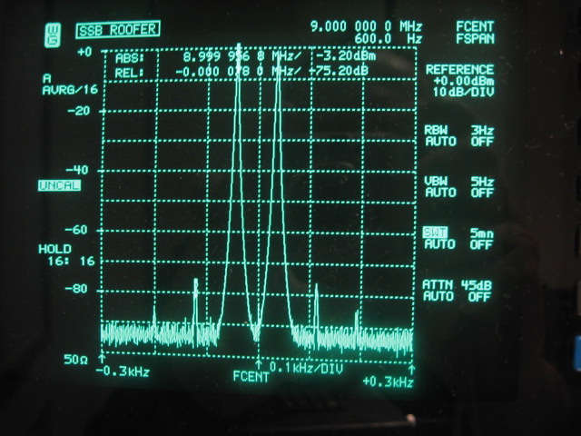
The following picture shows the 2-tone in-band results with only 80Hz separation. This picture has been made especially to compare the in-band IMD of the SSB filter with the in-band IMD of the CW filter. Average IP3 is +35.5dBm. Also visible are 5th order IMD products. 7th order is below the analyzers noise floor. It will be very challenging to make the IF-strip that follows this roofing filter to keep up with the +35dBm intercept point!
One more thing is worth mentioning regarding the IMD of the filter. I have used American Technical Ceramics ATC100-A quality chip capacitors, which are much smaller (0505-ish) than the smallest polystyrene capacitors, to reduce the size of the assembly. However an attempt to reduce the size even further by using the considerably smaller T37-6 toroids for the four L-matches gave disastrous results for the IMD performance of the filter. IIP3 dropped to a very 3rd order non-linear +46dBm at 4,5dBm input and to +42dBm at -9,5dBm input. For this reason the more linear black type 10 mix with size T50 is now used for all the toroids with minimal effect to the IL. Given the resulting IP3 linearity it does not seem necessary to go to even bigger T68-10 toroids in this design. The loaded Q of the diplexer, the hybrids and the L-matches are quite low.
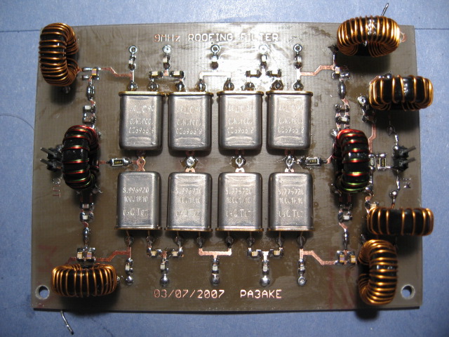
The following picture shows a preliminary standalone prototype version of the SSB roofing filter with ATC100-A chip capacitors. The size of the PCB is 70x90mm. The back-side of the double sided PCB is used as a full ground plane:
Pass band Insertion Loss
A reliable way to build a quad hybrid roofing filter is to build and analyze each section of the assembly separately before combining the individual sections to form a complete filter. On the PCB, a number of solder jumpers are available to facilitate this incremental build-up / measure-up approach. The following two pictures show the pass band of the two individual 4-pole sections without hybrids and diplexer:
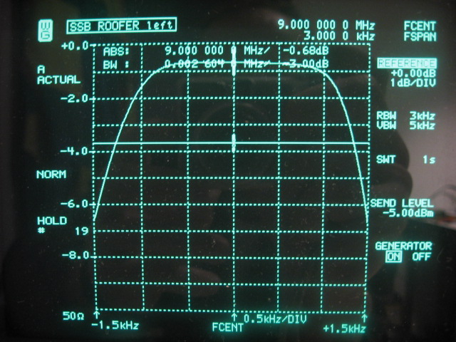
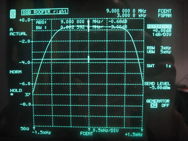
It is difficult to spot the differences between the two 4-pole sections as insertion loss and bandwidth as seen by the analyzer are very similar. Actually there is not much difference as the following overlay picture shows:
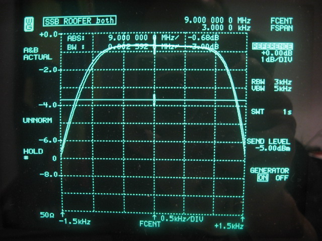
The 8 crystals are well matched and the curves almost overlap without any alignment using only fixed capacitors with standard values. I did select the crystals such that both sections would be as identical as possible, but note that I only had a batch of 10 crystals at my disposal! I also did not have a big stock of ATC100-A chip capacitors and maybe the results could be slightly better by selecting more identical capacitors in both filter sections or add trim capacitors to trim away any differences. For the SSB roofing filter this does not seem necessary.
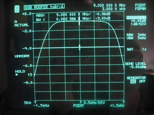
The next picture shows the insertion loss when both sections are combined with the two hybrids. The 2 hybrids add about -0.12dB to the insertion loss. The relay switching contributes an additional -0.20dB, so the IL becomes -0.96dB:
The following picture shows the insertion loss when the diplexer is added to form a completed filter assembly. The diplexer adds a minimal -0.08dB to the insertion loss:
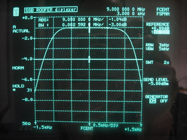
The completed roofing filter has an insertion loss of -1.04dB and a bandwidth of 2592Hz. It is centered well enough at 9.000MHz such that a sharp 8 or 10 pole 2.4KHz wide SSB crystal filter will fit perfectly within its pass band.
Stop band Insertion Loss
Low insertion loss in the pass band of the roofing filter is important to keep the noise factor (NF) of the frontend as low as possible. Good stop band performance is needed to attenuate strong signals outside the pass band as much as possible to avoid IMD in the subsequent stages of the receiver. The following picture shows the insertion loss in a 50KHz wide view of the completed filter:
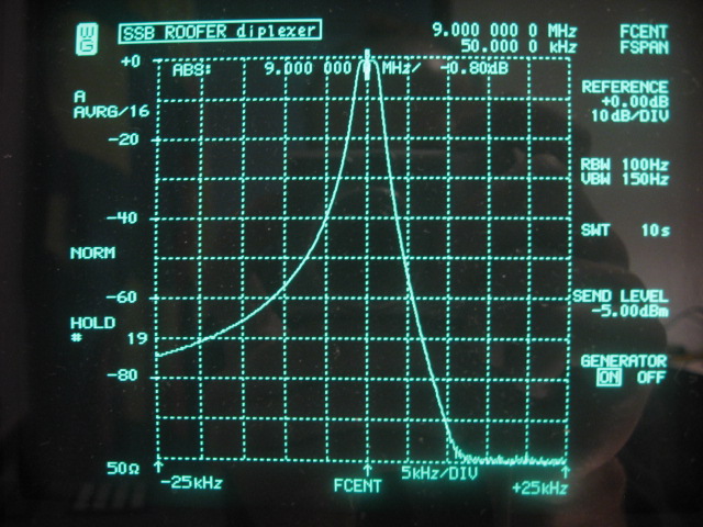
This picture clearly shows the by-design LSB behavior of the ladder filter. The -60dB bandwidth is an asymmetrical 18KHz. Blocking IL is around -105dB as measured with the N2PK VNA. The picture above is limited by the W&G analyzers 100dB range. The -105dB stop-band figure could only be obtained with an extra shield that divides the roofing filter section in two, shielding input from output. This shield must make good connection with both the top cover and the ground plane in order to be effective. Without the shield, only around -80dB stop-band could be reached with the box closed. This is caused by the L-match and hybrids toriods "seeing" each other directly, further worsened by reflections on the metal cover. Furthermore the crystal housings must be soldered to the ground plane, otherwise -105dB is not reached.
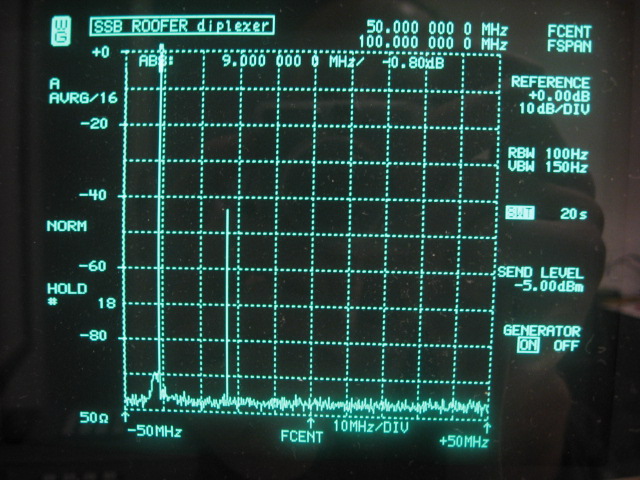
The following picture is a 100MHz wide view of the SSB filter. Stop-band is maintained over the entire range. The very low inductance ATC100-A capacitors and the PCB layout enable this. A spur response at 27MHz (3rd overtone) is visible at -45dB. Another spur at 45MHz (5th overtone) is missed, but actually exists at -70dB. Higher overtones, 7th and 9th are checked but are below -100dB.
Given the obtained stop band performance of the SSB roofing filter, a subsequent filter that provides the actual selectivity only has to provide a good shape factor, which is possible with analog and/or digital filters.
Wide band Return Loss
One of the design goals of the quad hybrid roofing filter is to form a perfect wideband 50 ohm resistive termination to the H-Mode mixer that precedes it in order to keep the IMD of the mixer down. The following picture is a 10KHz wide impedance plot with N2PK VNA as the mixer sees it. 50 ohm is rather well maintained, but both sections are not completely identical which causes the jump to 67 ohm at 9.002MHz.
The next picture again shows impedance, but now from 1-30MHz. It can be seen that from 6-14MHz the hybrids do their job to maintain 50 ohm. Outside that range the diplexer takes over. A tiny peak at the 3rd overtone can be seen as well.
CW Roofing Filter
Back to Roofing Filters
Back to the TOC
|