|
500Hz CW filter with QT crystals
The low motional resistance of the QT crystals allows for more than an SSB roofing filter! It turned out after a couple of simulations that is should be possible to build a CW roofing filter with a bandwidth of 500Hz and insertion loss around -2,5dB. The IL is 1,5dB more than with the SSB roofing filter but the reduced bandwidth more than compensates for that anyway (around 6dB!). The advantage of a 500Hz CW roofing filter is great. If the excellent out of band IMD can be maintained and the in-band IMD is not too bad, then the improvement gained in cutting away close-in IMD far outweighs the extra insertion loss, especially on bands were the noise figure of the frontend is not the most important factor anyway.
With a 500Hz bandwidth the design impedance of the ladder filter goes down and is approximately 50 ohm. This allows for the elimination of the L-matches, which simplifies the filter and helps to reduce the losses. Furthermore a 3-pole design is sufficient to provide more than enough "roofing" behavior because of the much higher loaded-Q of the filter. The 3-pole CW roofing filter is much more selective than the 4-pole SSB design.
In order to align the CW roofing filter accurately centered at 9.000000MHz, simulation showed that fixed value series capacitors like used in the SSB roofing filter to trim the filter in to place was not going to work. With the CW roofing filter the series capacitors must be trimmed precisely to align the filter correctly at 9.000000MHz. If a DSP back-end is used, the absolute center frequency of the CW roofing filter is not so important and can be compensated in software. This helps to improve the IL by 0.5dB! In that case, the series capacitors can be omitted completely, and the CW roofing filter will settle slightly above the series resonance of the crystals.
The following table shows the out of band (20KHz separated 2-tones) IMD performance of the CW roofing filter.
| CW Roofing filter with custom QT 9MHz crystals, 20KHz separated 2-tones |
| Level (dBm) |
IMD 1 (-dBc) |
IMD 2 (-dBc) |
IIP3 1 (dBm) |
IIP3 2 (dBm) |
IIP3 avg (dBm) |
| 4,5 |
101 |
102 |
54,0 |
55,0 |
55,5 |
| 2,5 |
104 |
106 |
54,5 |
55,5 |
55,0 |
| 0,5 |
109 |
110 |
55,0 |
55,5 |
55,3 |
| -1,5 |
113 |
114 |
55,0 |
55,5 |
55,3 |
| -3,5 |
116 |
117 |
54,5 |
55,0 |
54,8 |
| -5,5 |
119 |
120 |
54,0 |
54,5 |
54,3 |
Like the SSB roofing filter with QT crystals, this filter follows 3rd order behavior perfectly with an IIP3 of +55dBm. This is about +8dBm better than the OIP3 of the FSA3157 H-mode mixer on its best band: 40M. This ensures that the roofing filter is not a bottleneck with IMD in the frontend anymore and it has even enough margins to accommodate an even better mixer if that is possible at all!
The following table shows the IMD at a fixed input level of 0dBm at various 2-tone offsets (the 80Hz measurements are done at a level of -7dBm):
| CW Roofing filter with custom QT 9MHz crystals at -0.5dBm input level |
| 2-tone offset (KHz) |
IMD 1 (-dBc) |
IMD 2 (-dBc) |
IIP3 1 (dBm) |
IIP3 2 (dBm) |
IIP3 avg (dBm) |
| 100 |
115 |
112 |
57,5 |
56,0 |
56,7 |
| 50 |
114 |
113 |
57,0 |
56,5 |
56,7 |
| 20 |
112 |
113 |
56,0 |
56,5 |
56,2 |
| 10 |
114 |
113 |
57,0 |
56,5 |
56,7 |
| 5 |
115 |
108 |
57,5 |
54,0 |
55,7 |
| 2 |
97 |
97 |
48,5 |
48,5 |
48,5 |
| 1 |
85 |
92 |
42,5 |
46,5 |
44,5 |
| 0.5 |
74,0 |
73,2 |
37,0 |
36,6 |
36,8 |
| 0.2 |
49,6 |
54,8 |
24,8 |
27,4 |
26,1 |
| 0.1 |
49,2 |
50,4 |
24,6 |
25,2 |
24,9 |
| 0.08 |
61,6 |
62,8 |
23,2 |
24,6 |
23,9 |
Already at 1KHz separation the IIP3 nearly reaches +50dBm! The intercept point remains very good close-in until the tones are (partially) inside the pass-band and the IIP3 levels out at around +24dBm.
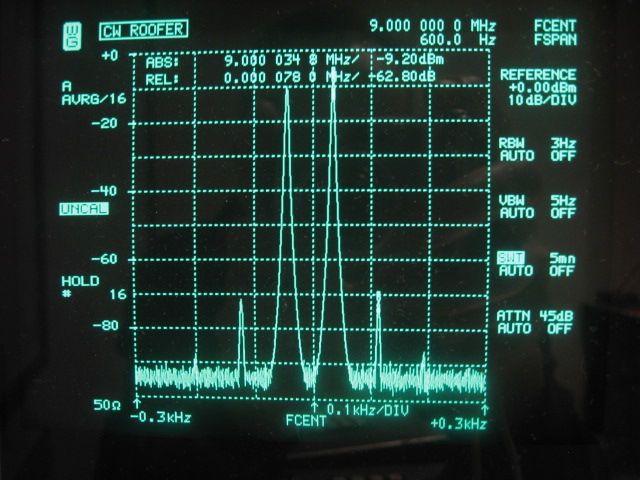
The following picture shows the 2-tone in-band results with only 80Hz separation. This picture has been made especially to compare the in-band IMD of the CW filter with the in-band IMD of the SSB filter. Average IP3 is +23.9dBm. Also visible are 5th order IMD products. 7th order is below the analyzers noise floor. When the SSB filter and CW filter are compared with each other regarding in-band IMD it is remarkable that the IIP3 is reduced by 12dB when the bandwidth is reduced by roughly a factor 4. This looks like 6dB per filter octave!
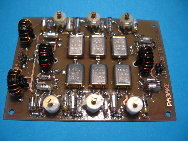
The following picture shows a preliminary standalone prototype version of the CW roofing filter with polystyrene capacitors. The size of the PCB is 70x90mm. The back-side of the double sided PCB is used as a full ground plane:
Pass band Insertion Loss
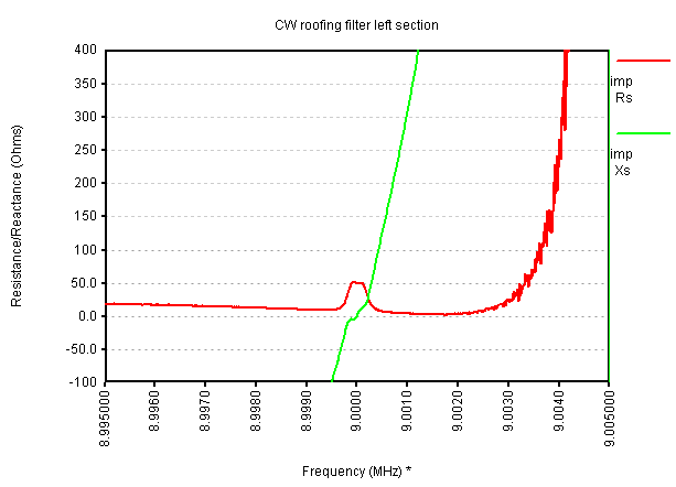
A reliable way to build a quad hybrid roofing filter is to build and analyze each section of the assembly separately before combining the individual sections to form a complete filter. In case of the CW roofing filter this approach is almost compulsory as both sections must be aligned correctly. This is almost impossible when they are combined with the hybrids. On the PCB there are a number of solder jumpers to facilitate this incremental build-up / measure-up approach. The following 2 pictures show the pass-band of the two individual 3-pole sections without hybrids and diplexer:
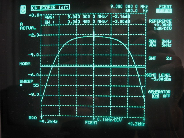
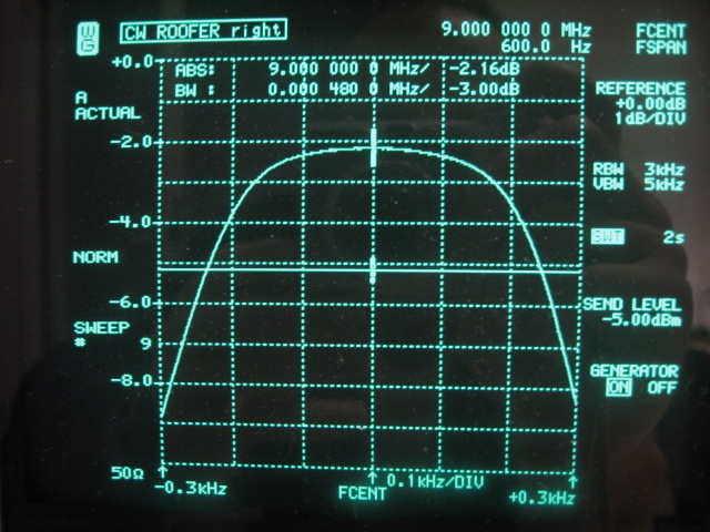
It is impossible to spot the differences between the two 3-pole sections as insertion loss and bandwidth as seen by the analyzer are identical. The two sections have been carefully aligned with the series trimmers to be identical. There is no difference as the following overlay picture shows. It looks like only one curve but brighter!
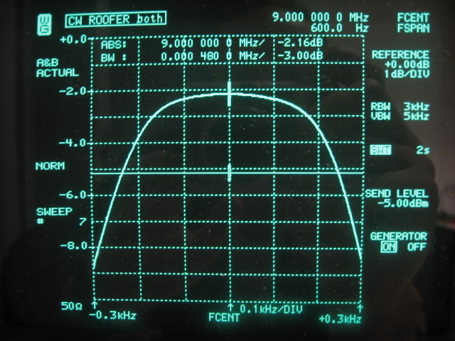
The 6 crystals are well matched and the curves do overlap after careful alignment with the series trimmers. I did select the crystals such that both sections would be as identical as possible.
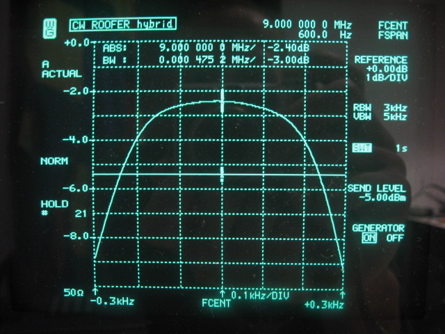
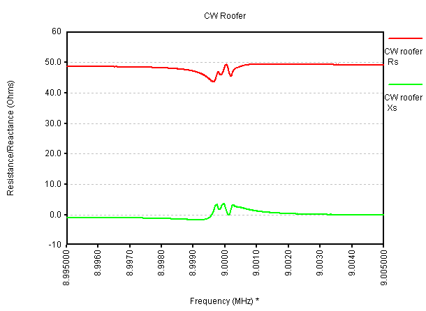
The next picture shows the insertion loss when both sections are combined with the two hybrids. The 2 hybrids add about -0.08dB to the insertion loss. The relay switching contributes an additional -0.16dB, so the IL becomes -2.40dB:
The following picture shows the insertion loss when the diplexer is added to form a completed filter assembly. The diplexer adds a minimal -0.04dB to the insertion loss:
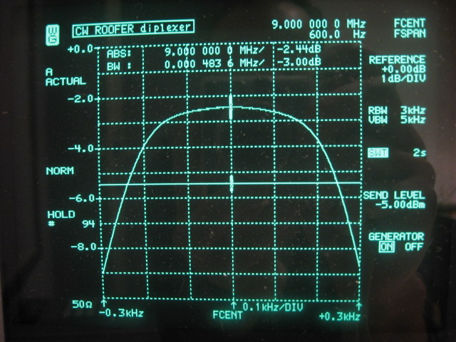
The completed roofing filter has an insertion loss of -2.44dB and a bandwidth of 483Hz. It is centered precisely at 9.000000MHz.
Stop band Insertion Loss
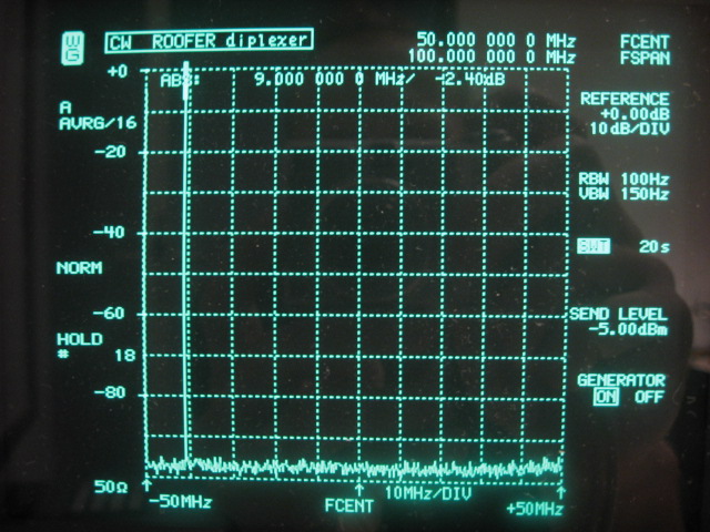
Low insertion loss in the pass-band of the roofing filter is important to keep the noise factor (NF) of the frontend as low as possible. Good stop band performance is needed to attenuate strong signals outside the pass-band as much as possible to avoid IMD in the subsequent stages of the receiver. The following picture shows the insertion loss in a 50KHz wide view of the completed filter:
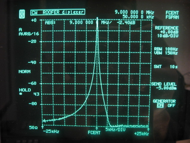
This picture clearly shows the by-design LSB behavior of the ladder filter. The -60dB bandwidth is an asymmetrical 5.2KHz. Blocking IL is around -105dB as measured with the N2PK VNA. The picture above is limited by the W&G analyzers 100dB range. The -105dB stop-band figure could only be obtained with an extra shield that divides the roofing filter section in two, shielding input from output. This shield must make good connection with both the top cover and the ground plane in order to be effective. Without the shield, only around -90dB stop band could be reached with the box closed. This is caused by the direct coupling of input and output worsened by reflections on the metal cover. Furthermore the crystal housings must be soldered to the ground plane, otherwise -105dB is not reached.
The following picture is a 100MHz wide view of the CW filter. Stop-band is maintained over the entire range. The very low inductance ATC100-A capacitors and the PCB layout enable this. A spur response at 27MHz (3rd overtone) is missed by this sweep, but is actually there at -55dB. Another spur at 45MHz (5th overtone) is also missed, but actually exists close to the analyzers noise floor. Higher overtones, 7th and 9th are checked but are below -100dB.
Given the obtained stop-band performance of the CW roofing filter, a subsequent filter that provides the actual selectivity only has to provide a good shape factor, which is possible with analog and/or digital filters.
Wide band Return Loss
One of the design goals of the quad hybrid roofing filter is to form a perfect wideband 50 ohm resistive termination to the H-Mode mixer that precedes it in order to keep the IMD of the mixer down. The following picture shows a 10KHz wide impedance plot with N2PK VNA of a single 3-pole filter section, so just the ladder filter without hybrids and diplexer. It is obvious that 50 ohm is maintained only within the pass-band. Outside the pass-band the impedance varies from 0 to infinity and reflection will be almost 100% for sure!
The following picture shows the impedance of the entire CW roofing filter and demonstrates the effect of the hybrids and diplexer. 50 ohm is accurately maintained as both sections are almost completely identical.
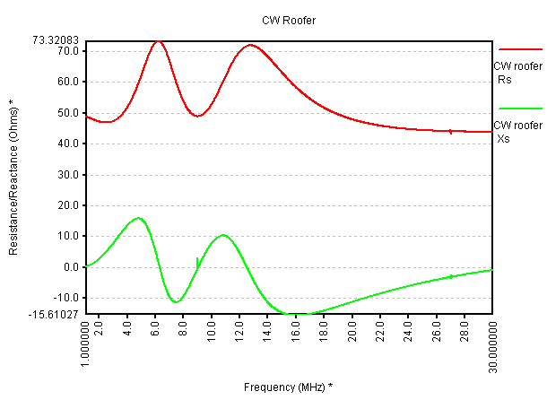
The next picture again shows impedance, but now from 1-30MHz. It can be seen that from 6-14MHz the hybrids do their job to maintain 50 ohm. Outside that range the diplexer takes over. A tiny peak at the 3rd overtone can be seen as well.
SSB Roofing Filter
Back to Roofing Filters
Back to the TOC
|