|
FSA3157 H-Mode mixer with I2C DAC control
The evaluation of the different H-Mode mixer configurations has led to a 'production' H-Mode mixer design with I2C DAC controlled squarer and mixer bias point. The DAC's should be programmed to give the mixers its optimum performance depending on the LO frequency. A single adjustment per amateur band provided with a lookup table in the receiver's u-Controller will probably be sufficient.
The squarer DAC is the more useful of the two, and governs the balance of the mixer and hence the IF feed through properties and DDS spur isolation.
The bias-point DAC is not needed with some transformers, because some are for yet unknown reasons rather insensitive to the bias-point. If needed the DAC is used to adjust for minimum IMD per amateur band.
The following picture shows the mixer section of the frontend board:
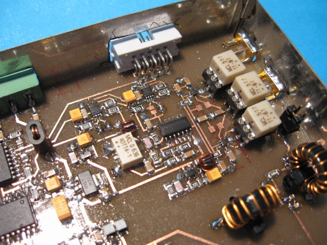
DIP6 sockets are used as transformer mounts for flexibility regarding the choice of transformers. At this moment they are populated with MCL T1-6T's, the best performer with respect to IMD. Even if it is 100% decided which transformers to use, the DIP sockets can still be useful. They allow for easy exchange of the transformers with the purpose of finding the most balanced mixer configuration. I have always found 1 or 2 configurations that have the deepest IF feed through dip among the 6 possible configurations. We are talking about sometimes 10-15dB of IF feed through improvement, caused by transformer production tolerances!
The LO impedance step-up transformer on the picture is an expensive MCL ADTT4-1, but it can equally well be a simple homemade 1:4 transformer with a BN43-2402 binocular core and 7 bifilar turns.
Also visible are the two small I2C DAC's with MSOP-08 packages. The one to the right controls the mixers bias-point. If this DAC is not mounted, then two 1206 resistors (R14 and R15) should be mounted instead to give a fixed bias-point. Don't mount both the DAC and those resistors! Two empty 1206 slots are available for this purpose and are located close to the centre transformer. Use the resistive divider if you don't have the means to measure the IP3 of the mixer!
In order to be able to do measurements on the mixer alone or on the roofing filters alone, there is a small jumper block between the mixer transformers and the diplexer toroids. Normally it is jumpered as on the picture to feed the diplexer with the IF-port of the mixer. However this jumper block allows the mixer IF-port to be inspected with for instance a spectrum-analyzer or the roofing filter's can be fed directly with a signal generator or network analyzer.
All three I2C devices on the frontend board have solder jumpers to be able to configure their I2C port addresses. The datasheets of these IC's provide all the info needed, including the programming details and bit assignments. Furthermore SJ13 and SJ14 can be used to add pull-up resistors to the I2C bus. This should be done for the last device on the bus only, especially if the bus is not very short. The DAC's have a 12-bit precision, which provides the accuracy needed especially for the squarer DAC. Even though, with some transformers, the optimum feed through dip can be so steep that even 12 bits are no luxury!
It can be seen from the schematic (sheet 4) that bit0 of IC9 (I2C 8- bit I/O expander, PCF8574A) is used to choose the desired roofing filter. Bit0=0 => SSB-roofer, Bit0=1 => CW-Roofer.
Performance
The mixer on the frontend board is the 3rd FSA3157 mixer I build and fully tested. The results are reproducible and in line with the previous results. The following table shows the results of the 'production' mixer when equipped with MCL T1-6T transformers:
| FSA3157 + T1-6T + 74AC04 |
Vdd = 7.0V, Vbias = 2.5V |
Best bias |
| Band |
BPF |
mixer |
MDS -dBm |
IF rej |
spur |
mixer IIP3 (dBm) @ 20KHz spacing |
Bias |
| IL |
CL |
- |
+ |
|
avg |
-6 |
-3 |
0 |
+3 |
+5 |
|
| -dB |
-dB |
BPF |
BPF |
-dB |
dB |
dBm |
dBm |
dBm |
dBm |
dBm |
V |
| 160 |
0,64 |
4,76 |
134,0 |
133,0 |
58,0 |
|
|
|
49,2 |
|
|
2,5 |
| 80 |
0,56 |
4,84 |
134,0 |
133,0 |
58,0 |
|
47,7 |
50,2 |
51,8 |
51,7 |
51,2 |
2,5 |
| 40 |
1,20 |
4,80 |
134,0 |
132,5 |
57,2 |
|
|
|
51,8 |
|
|
2,5 |
| 30 |
1,60 |
4,80 |
134,0 |
132,5 |
57,0 |
|
|
|
51,4 |
|
|
2,5 |
| 20 |
1,40 |
4,88 |
134,0 |
132,5 |
58,0 |
|
|
|
50,3 |
|
|
2,5 |
| 17 |
1,48 |
4,92 |
134,0 |
132,5 |
59,2 |
|
|
|
49,1 |
|
|
2,5 |
| 15 |
1,44 |
4,96 |
134,0 |
132,5 |
57,6 |
-4,90 |
|
|
48,8 |
|
|
2,5 |
| 12 |
1,60 |
5,12 |
134,0 |
132,0 |
58,0 |
|
|
|
46,7 |
|
|
2,5 |
| 10 |
1,80 |
5,12 |
133,5 |
131,0 |
64,4 |
|
|
|
45,5 |
|
|
2,5 |
| 6 |
3,36 |
5,24 |
132,5 |
127,5 |
52,8 |
|
|
|
39,4 |
|
|
2,5 |
| 4 |
|
5,36 |
129,0 |
|
54,0 |
|
|
|
39,8 |
|
|
2,5 |
Especially spur behavior is much better than with my earlier two FSA3157 mixers builds with T1-6T transformers. At -4.9dB below MDS average spur level this mixer is really quiet regarding the +100 spurs I have mapped on 15M. This is probably due to the improved PCB layout and roofer shielding compared to my more experimental previous setup.
Back to Frondend Board
Back to the TOC
|