Low phase noise reference clock
The AD9910 and AD9912 high speed DDS chips can both be clocked at 1GHz, allowing for output signals up to 400MHz in the baseband. The quality of the DDS output signal depends to a high degree on the quality of the DDS reference clock signal. Therefore a lot of attention has to go the 1GHz reference clock in order to make the DDS a success. The following criteria are important to the reference clock:
-
Phase noise
Any phase noise of the reference clock, when scaled down (6dB/octave) to the output frequency of the DDS, that is in excess of the residual phase noise of the DDS chip will dominate the residual noise and should be avoided. Further out this is usually not a problem, but close in things get tougher. At less than 1KHz we need really ultra low noise SC-cut crystal oscillators to beat the residual noise of the chip. Luckily for the HF amateur LO, very low phase noise at 1KHz and inwards, inside the roofing filter so to speak, is not that important.
-
Spurious responses
Any spurs, especially sub-harmonic and non-harmonic spurs, should be kept as low as possible in order to decrease the possibility of DDS spurs. Odd harmonics of the reference clock are unimportant, because the squaring-up of the clock signal inside the DDS chip will introduce them anyway. Of course also spurs based on reference clock and output frequency due to the finite precision of the DAC are inevitable. Nothing can be found in the literature on how much spur suppression is really needed, so if it is not too difficult, we should "go for broke" in getting the spurs really down.
-
Frequency stability
How much frequency stability is needed is a bit depending on personal taste or need for perfection. The trend in modern amateur equipment is more and more precision; going from uncompensated XO's which were common in the past to TCXO's and even OCXO's today. Very low phase noise often comes together with very good stability as SC-cut VHF crystal oscillators are often packaged as OCXO's.
Frequency multiplication
Although the AD9910 and AD9912 still have the on-chip reference clock PLL multiplier to multiply an external lower frequency clock to 1GHz, that feature will not be used. Residual noise plots in the datasheet with the PLL in use show clearly that this is not the way to go when low phase noise is important.
The experimental 1GHz clock now in use builds further on the work done by Giuliano Carmignani, I0CG, with the 500MHz clock for his well known AD9951 DDS board. Starting point is a 100MHz low noise crystal oscillator, which is squared up and multiplied by 5 through harmonic selection with helical filters. This 500MHz signal, after some amplification, is multiplied by 2 with a diode frequency doubler to 1GHz and once more filtered with helical filters.
There is quite an advantage in splitting the 10x multiplication up in 2 separate steps. First of all, the conversion loss of each multiplier step is less which makes it easy to maintain the dynamic range of the original 100MHz signal, which would otherwise lead to an extra elevated noise floor. Second, the removal of sub harmonics (the harmonics of the 100MHz signal) in the output signal is much easier. The end result is that the multiplier has little or no sub harmonic spurs and adds little excess phase noise except the unavoidable 20dB inherent to a 10x frequency multiplication. We will get those 20dB back anyway at the output of the DDS, because the DDS acts as a digital divider, reversing the process.
In preparation to the LO-DDS project, I have collected a couple of good 100MHz oscillators on eBay. Ranging from surplus Wenzel and Bliley OCXO's to a TCXO and a few more modest uncompensated oscillators although with reasonable phase noise performance. On top of this, thanks to Colin Horrabin, G3SBI, and the Daresbury Laboratory in Warrington UK, I have 2 very low noise Premium Wenzel Sprinter OCXO's at my disposal, in order to be able to do tests, measure phase noise and in general find out what is possible with DDS in practice when the reference clock is not the main contributor to the phase noise!
All testing is done using the Premium Wenzel Sprinters. In a later stage the more modest oscillators will be put to the test in order to find a good balance between price and performance. The end goal of the LO project is an LO-DDS with good close-in phase noise performance made up with affordable off-the-shelf, non-surplus relatively easy to get components, such that it is reproducible for others. The following table shows the specified and the actually measured phase noise of the Wenzel 501-04517D oscillator:
| 100MHz Wenzel, model 501-04517D |
| Offset (KHz) |
PM-noise (dBc/Hz) |
| Specified |
Measured |
| 0.05 |
|
-124.1 |
| 0.1 |
-130 |
-131.1 |
| 0.2 |
|
-139.1 |
| 0.5 |
|
-149.6 |
| 1 |
-155 |
-157.1 |
| 2 |
|
-161.6 |
| 5 |
|
-165.6 |
| 10 |
-165 |
-166.1 |
| 20 |
-167 |
-166.1 |
| 50 |
|
-166.1 |
| 100 |
|
-166.1 |
| 200 |
|
-166.1 |
| 500 |
|
-166.1 |
My measurements slightly outperform the specs from Wenzel for the 501-04517D. The phase noise is measured using the Quadrature Mixing Method with the two units available to me. One as the DUT, one as the reference. Assuming that both oscillators have about the same phase noise level, an extra 3dB was subtracted from the measured phase noise to account for the RMS added, equally strong noise of two units. It is uncertain where exactly the real noise floor of the oscillator will end up. The measured -166.1dBc/Hz is the limit of my homebrew PM-noise test set. The following graph plots the measured values of the 501-04517D against a logarithmic frequency scale. The scales are in dBc/Hz and KHz:
The following screen shot shows the first 4KHz of the phase noise when made visible on the spectrum analyzer. Unfortunately the SNA62 only supports linear frequency sweeps in spectrum analysis mode:
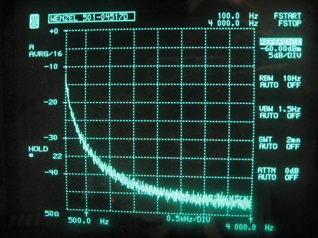
The correction factor to be used to turn the analyzers dBm scale into dBc/Hz for this picture is -57.3dB. More details on how to scale the analyzer plot is found here: Quadrature Mixing Method. Within the maximum offset from carrier (500KHz) that I can measure with my phase noise test set, I have found no spurs at all with this oscillator. It is completely clean down to the thermal noise floor:
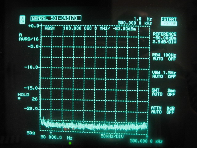
The correction factor for this picture is -62.3dB. Theoretically, the AD9910 DDS could produce -144.6dBc/Hz at 100Hz out with this reference clock when scaled down to an output frequency of 21.1MHz. (-131.1 - 20 * 10log(100/21.1)) The residual phase noise plot found in the AD9910 datasheet promises about the same: -145dBc/Hz at 100Hz out on 21.1MHz, which makes this oscillator an ideal reference oscillator for evaluating the AD9910 DDS at offsets as close-in as 100Hz!
1GHz results
After a 10x frequency multiplication, the resulting 1GHz multiplied Wenzel signal looks as follows directly on the spectrum analyzer in a very narrowband 500Hz plot at 1GHz:
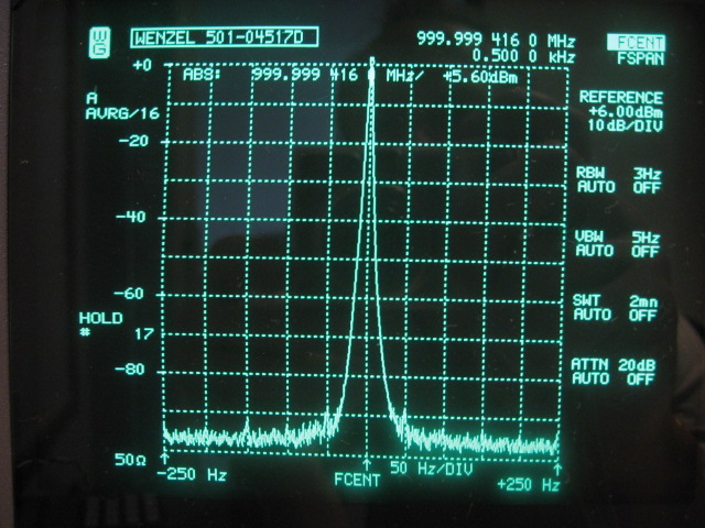
The dynamic range of the SNA62 is not good enough to directly show the noise sidebands of this signal. All we can see is that at least -95dBc/3Hz is achieved 50Hz out, which would translate in -100dBc/Hz at 50Hz out. Scaled down to 100Mhz that gives -120dBc/Hz, which is a almost 4dB worse than the measured phase noise at that offset (-124.1dBc/Hz). So we are looking at the noise floor of the analyzer and possibly the phase noise of its LO through reciprocal mixing! This is exactly why we need a specialized test set to suppress the carrier and amplify the noise side bands to see anything reliably at these low signal levels so close to the carrier. Unfortunately, my phase noise test set is not capable to measure at 1GHz, because its DBM is specified only up to 500MHz. Finally, note that this picture was taken with a slightly different alignment than the next picture. The clock is now aligned to give a bit more output: +8.4dBm.
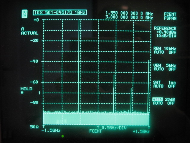
The following plot is a 3GHz wide plot to get a first impression on the presence or absence of unwanted signals in the output spectrum of the 1GHz reference clock signal. The noise floor is the analyzers noise floor. Except for second and third harmonic, the only visible strong spur is at 2.5GHz. This is the third harmonic of the internal 500Mhz signal which is apparently not fully suppressed by the 1GHz helicals. All other spurs are below the -90dBc level in this plot.
Individual 'deep' inspection of the 100MHz mother oscillator related sub harmonic spurs results in the following table:
| Sub harmonic 100MHz spurs relative to 1GHz |
| GHz |
dBc |
| 0.1 |
< -120 |
| 0.2 |
< -120 |
| 0.3 |
< -120 |
| 0.4 |
< -120 |
| 0.5 |
-113 |
| 0.6 |
< -120 |
| 0.7 |
< -120 |
| 0.8 |
< -120 |
| 0.9 |
< -120 |
| 1.0 |
0 |
| 1.1 |
< -120 |
| 1.2 |
< -120 |
| 1.3 |
< -120 |
| 1.4 |
< -120 |
| 1.5 |
-101 |
| 1.6 |
< -120 |
| 1.7 |
< -120 |
| 1.8 |
< -120 |
| 1.9 |
< -120 |
| 2.0 |
-52 |
| 2.1 |
< -120 |
| 2.2 |
< -120 |
| 2.3 |
< -120 |
| 2.4 |
< -120 |
| 2.5 |
-65 |
| 2.6 |
-107 |
| 2.7 |
-104 |
| 2.8 |
-101 |
| 2.9 |
-108 |
| 3.0 |
-39 |
| 3.1 |
-88 |
| 3.2 |
-101 |
| 3.3 |
< -120 |
Most sub harmonics are 120dB or more below the carrier. The main exception is 2.5GHz at -65dBc. An additional miniature MCL LPF in the final release of the reference clock design should suppress this a bit further. For reference: The Wenzel Agate I oscillator that produces 1GHz with internal multipliers from its 100MHz Sprinter like source is specified at -80dBc or better for sub harmonics.
Prototype Assembly
The following picture shows the first 1GHz reference clock prototype build.
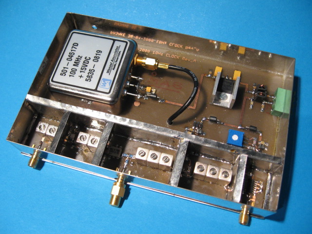
The multiplier chain goes from right to left: 100MHz squarer, 500MHz helical with MMIC amp, 500MHz helical with MCL doubler, 1GHz helical with MMIC amp, 1GHz helical with SMA output. Twice the number of helical filters has been used, more than strictly needed to just do the multiplications! The stop-band of the TOKO filters is rather poor due to their construction and extra filters are needed to obtain good sub-harmonic suppression.
The output level of the 1GHz reference clock is +8dBm, which leaves enough headroom for a power splitter to clock multiple AD9910's if needed. Also note the use of shielded compartments for each filter section. Like with the shielding in the frontend box, it is absolutely essential that the compartments make firm contact with the top cover. Without these extreme precautions the < -120dBc result for most sub harmonic spurs cannot be reached!
1GHz phase noise estimation
The following graph does not show a real measured result, but it is a realistic estimation of the PM-noise of the Wenzel 501-04517D oscillator multiplied by a factor of 10 to 1GHz:
An ultimate noise floor of -172dBc/Hz of the Wenzel is assumed and 20dB + 2dB extra is added for the 10x multiplication. The 1GHz helical filters cutoff at 10MHz and their measured filter curve has been taken into account. The scales are in dBc/Hz and KHz.
1GHz Reference Clock
AD9910 Prototype Board
AD9910 and SSB-Noise
AD9910 and PM-Noise
Back to Design Choices
Back to the TOC
|