IF Notch Board
In a frontend the IF frequency must be blocked as much as possible before the mixer, in order to prevent strong signals to blow straight in to the IF and cause interference independent of the frequency being listened at. This is known as the IF or (0,1) mixer spur. Just think of what an S9 + 50dB woodpecker around 9MHz could do if the IF spur is not drastically blocked!
In an up-conversion frontend this spur can be suppressed by the same low pass filter that suppresses the image, which is an advantage! In a down-conversion frontend, like the one described here, the BPF filters sometimes are not sufficient to block this spur and an additional notch filter is needed.
The design goal is to about completely eliminate the IF spur with as little impact as possible to the bands nearby, 40M and 30M in this case. A total 9MHz block of at least -120dB is the goal, with preferably less the 0.5dB extra insertion loss on 30M and 40M. The IF block consists of three components in the following order:
-
The BPF that is actually switched in
-
The notch filter
-
The mixer's IF rejection
The BPF with the worst rejection at 9MHz is the 30M BPF with only about 20dB. The H-Mode mixer will have at least 55dB IF rejection. So the notch should at least provide another 45dB. This is easily achievable.
The following circuit is used to produce a steep hole at 9MHz. It is a 3rd order Butterworth band reject design optimized to get the steepest dip with minimal impact on 30M and 40M.
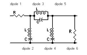
Usually a notch filter with only one shunt series trap is used in most frontends. Such a 2nd order notch can provide adequate attenuation at 9MHz provided that really high Q coils are used. However the 3rd order design presented here improves on this by even better attenuation at 9MHz combined with fewer losses at the two adjacent amateur bands.
The critical factor to success here is the Q of the 3 inductors! The series-shunt trap coils have an inductance that will be easy to produce with very high Q by using the bigger toroids like T80 and beyond. The "problem child" is dipole 3, the parallel trap. With only 200nH it turned out to be impossible for me to produce a high enough Q coil at 9MHz by simply using toroids. The solution was to let go the easy going iron powder and use a rather big conventional air coil instead!
The following table shows the theoretical and practical values used in the notch:
| 9MHz Notch, Fc=9000KHz, -3dB BW=1350KHz |
| Dipole |
Design |
Implementation |
Inductor |
| R (ohm) |
L (uH) |
C (pF) |
R (ohm) |
L (uH) |
C (pF) |
C (pF) ATC |
Core |
# turns |
wire (mm) |
| 1 |
50 |
|
|
50 |
|
|
|
|
|
|
| 2 |
|
7.38 |
42.4 |
|
6.80 |
39 + 5 |
39 + 5 |
T80-6 |
39 |
0.45 |
| 3 |
|
0.212 |
1477 |
|
??? |
1200 + 180 + 120 |
1000 + 390 + 120 |
air (10mm diam. 7mm length) |
5 |
0.80 |
| 4 |
|
7.38 |
42.4 |
|
6.80 |
39 + 5 |
39 + 5 |
T80-6 |
39 |
0.45 |
| 6 |
50 |
|
|
50 |
|
|
|
|
|
|
The practical capacitors are made up from combinations of standard values and trimmers. The first column shows the values I used with Polystyrene capacitors. The other column shows values when ATC100-B chip capacitors are used. Dipole 2 and 4 use a 5p trimmer. Dipole 3 has a 120p trimmer. This is the only filter where fine tuning is done with trimmers instead of fiddling with the toroids. This shows the precision needed to correctly align this filter. A network analyzer such as N2PK VNA is highly recommended. Aligning this notch filter without a (scalar) network analyzer will be challenging as many sub-optimal solutions are possible with a 3rd order design...
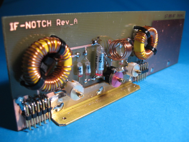
The following picture shows the resulting 1/2 height eurocard plug-in board:
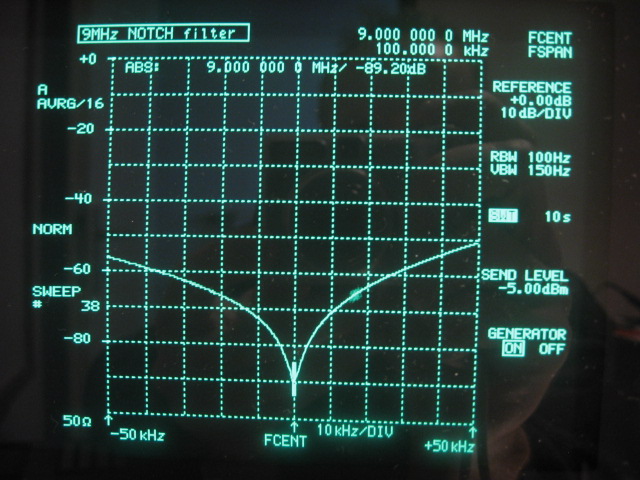
The following picture shows the 100KHz close in plot centered at 9MHz. A reliable rejection in excess of 80dB is possible. Even more is possible but it will be questionable if that can be maintained over time, temperature and movement... In simulation with coils at a Q of 250 the dip reaches also -89dB!
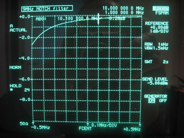
The 4MHz wide band plot shows that losses at the 2 adjacent amateur bands will be rather minimal:
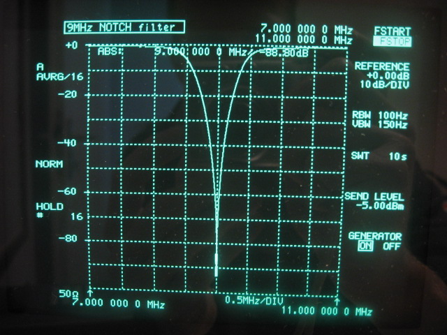
When we zoom in at 10MHz, the penalty at 30M comes out at about -0.28dB. In simulation with Q's of 250 it was -0.27dB!
When we zoom in at 7MHz, the penalty at 40M is only -0.12dB. I simulation it came out at -0.05dB.

The presented 3rd order Butterworth notch filter will give an overkill of IF rejection with minimal extra losses at the adjacent amateur bands. Only 45dB is needed and 80dB is easily reached! The 35dB of excess IF rejection can possibly be put to good use by aligning the H-Mode mixer for best spur reduction on the high bands rather than best IF rejection!
The notch is placed behind the BPF's in the signal chain. This is done to minimize the spectrum exposed to the notch filter and hence any IMD2 or IMD3 introduced by the imperfect iron powder T80 cores.
As mentioned before, alignment of the notch is critical. The three trimmers have been made accessible to the outside to tune the filter when it is in its final enclosure.
In order to eliminate the alignment difficulties it might be possible to replace this LC circuit with a quartz notch filter. This possibility looks promising and might be further investigated at some point, priorities permitting!
PCB artwork and schematic for the IF notch board in PDF format.
Mother Board
I2C Controller Board
Attenuator Board
Band Pass Filter Board(s)
Back to Frondend Input Band Pass Filters
Back to the TOC
|