|
I2C Controller Board
The 12 BPF filters are relay-switched and the control is handled through the well-known I2C 2-wire serial protocol. The board has a 16 bit I2C I/O-extender (PCF8575) with 2 8-bit relay drivers (ULN2803A) and 12V and 5V LDO regulators. The 16 bits are sufficient to control the relays of up to 12 BPF boards and a 4 stage step attenuator.
The following picture shows the populated 1/2 height eurocard plug-in board:
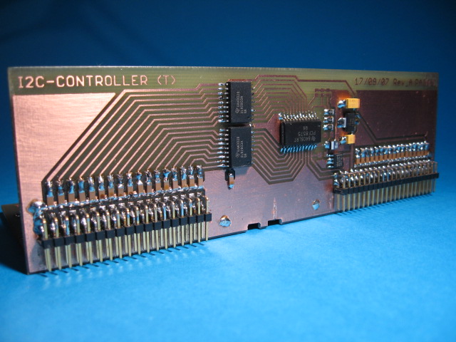
The design is straight forward without many complications. The only important detail is that the relay control lines that are routed to both ends of the board are thoroughly RF isolated / decoupled from each other with LC filters. This is to prevent a signal leak that bypasses the BPF's through these lines with parasitic coupling. It is a double sided PCB. The other side holds the tracks that DC connect the relay control lines for each side and the SMD coils, 2 per control line.
PCB artwork and schematic for the I2C controller board in PDF format
The following notes regarding the schematic:
-
C17, C63, C62 are tantalium capcitors.
-
R4 and R5 are 2K2 and should only be installed if this I2C slave is the last device on the bus.
-
R1, R2, R3 are 10K and the address of the I2C slave can be set with the corresponding solder jumpers. See the PCF8575 datasheet for more info.
-
L1..34 are 1206 SMD inductors of 1.8uH. Some 1210 SMD inductors may fit also, but make sure there are no short cuts!
Mother Board
Attenuator Board
Band Pass Filter Board(s)
IF Notch Board
Back to Frondend Input Band Pass Filters
Back to the TOC
|