Reproduction of ADI's excellent PM-noise results
With the AD9910 noise plateau now being identified as AM-noise, which at least in theory can be scrubbed off easily, the next thing to do is to try to reproduce the excellent PM-noise results measured by ADI, to verify that the pure DDS HF-LO is still a possibility. The two measurement methods used so far, the reciprocal mixing method and the notch filter method, are not suitable, because they are sensitive to both AM-noise and PM noise. One of the methods that measures only PM-noise and rejects AM-noise at least to a large degree is the Quadrature Mixing Method.
So I build a simple phase-noise-test-set, consisting of a phase detector, a low noise amplifier and a PLL active loop filter that together with a clean reference oscillator and a general purpose spectrum analyzer forms a precise PM-noise measurement system. A 100MHz Premium Sprinter oscillator from Wenzel is used as the reference oscillator. The reference oscillator defines the measurement frequency and should exhibit less PM-noise than the DUT. A synchronous digital divider makes it possible to measure also PM-noise apart from 100MHz at 50MHz, 25MHz, 16.67MHz, 12.5MHz, 10MHz and 8.33MHz with the same Wenzel oscillator as the reference. Using this new "toy", I recorded the following PM-noise plots with the AD9910 evaluation board (scales are in dBc/Hz and KHz):
The above PM-noise plots are much better than the AM-noise plots measured before! The noise plateau that extended all the way to 200KHz out has mostly disappeared. But still this is not quite as good as what we are looking for. The four different series scale correctly with the working frequency, about 6dB per octave, but a noise plateau effect although much less severe still exists. The plateau scales correctly with the working frequency, so it is really PM-noise this time!
The remaining PM-noise plateau turns out to have two different but similarly contributing sources and both are power supply related. First, an issue is found with the onboard voltage regulator that powers the 100MHz squarer circuit in the 1GHz reference clock subsystem. Second, the evaluation board is powered with ordinary LM317 voltage regulators, because power supply noise did not make any difference in earlier test with the excess AM-noise. After fixing the clock PSU problem and hooking up the low noise homebrew regulators to the evaluation board, the result looks as follows (scales are in dBc/Hz and KHz):
This is a vast improvement indeed! The 12.5MHz series is beginning to approach the 14.3MHz series by ADI now, but something "funny" is still going on. The 100MHz series is better than the 50MHz series from 5KHz and outwards! The 100MHz series is taken without the digital divider unlike the other series. It appears that the digital divider, used to divide the 100MHz reference clock down to the other working frequencies, is now becoming a dominant PM-noise contributor at these lower noise levels!
Up to this point my assumption had been that the digital divider in the measurement setup could be seen as an "ideal" circuit without any significant PM-noise contribution. In other words I thought it was free of any significant residual noise, so a divide by 2 should result in 6dB less PM-noise. That is about the same thing as stating that the divider is jitter-free, which is not the case in the real world. The divider circuit is a configurable synchronous Johnson counter build with 74AC74 D-type flip-flops. The 74AC74 allows clocking well beyond 100MHz, typically 160MHz according to the datasheet. Soon a second identical synchronous Johnson counter was build and its residual noise was measured with the following results (scales are in dBc/Hz and KHz):

The graph clearly shows that when the 100MHz Wenzel is divided down, the resulting PM-noise is not reduced with 6dB/octave, but actually gets stronger. The reason is that the jitter and the resulting residual noise of the divider is stronger than the divided down PM-noise of the 100MHz clock signal, so it completely dominates the end result! The residual noise of the divider is following a slope of around 3dB/octave. Very close-in the divider can give some improvement, because the clock signal follows a much steeper 6dB/octave slope.
Now if we compare the "second attempt" AD9910 PM-noise plots with the synchronous divider plots, then it becomes obvious that we are measuring mostly the Johnson counter of the measurement setup rather than the AD9910 DDS!
Residual phase noise plots are usually not shown in the datasheets of digital building blocks, at least not in case of the 74AC logic family. However the datasheet of the AD9515, a configurable high speed divider, shows residual phase noise plots for the various configurations possible with that device. It supports LVDS, LVPECL and CMOS logic. This yields the following graph, when normalizing to a 50MHz output frequency from the divider (scales are in dBc/Hz and KHz):
There is very good agreement between my 74AC74 and the AD9515 in CMOS mode! The LVPECL series is especially promising and seems good enough to measure the AD9910 without dominating the results, but for now I am limited to 100MHz only with the Wenzel reference clock.
With the Johnson counter eliminated as a "sneaky" source of PM-noise in the measurement setup, I could now further zoom-in at the PM-noise performance of the AD9910 itself, but only at 100MHz.
At these very low PM-noise levels, the power supplies do play a major role in the performance. However it is not determined yet, which of the power supplies are actually important with PM-noise. Especially the 2 analog power rails are expected to be sensitive. Common sense predicts that the 3.3V analog power rail will contribute to AM-noise as it powers the DAC. AM-noise however is already dominated by the "DACBP issue", so the 3.3V analog rail is probably not so important. So what about the 1.8V analog rail that powers the 1GHz clock signal path? The next graph maps the 4 different analog power supply combinations possible with LM317's and the low-noise homebrew regulators build earlier when I was chasing the AM-noise. (scales are in dBc/Hz and KHz):
The analog 3.3V power supply plays no significant role in the PM-noise performance. The results with the LM317 regulator and the low noise regulator are practically overlapping each other. On the contrary, the analog 1.8V power supply is quite sensitive to PM-noise, because the by now well known and dreaded "noise plateau effect" is showing up once again! We already knew that the LM317 gives a penalty to the phase noise, but now we know which power supply is important! The other observation that can be made is that the LM317 regulator actually improves things close-in, < 2KHz! This means that the homebrew low noise regulator needs further improvement at low frequencies.
The following spectrum analyzer screen shot shows the noise of the 1.8V digital rail with the LM317 regulator powering most of the digital circuits of the AD9910:
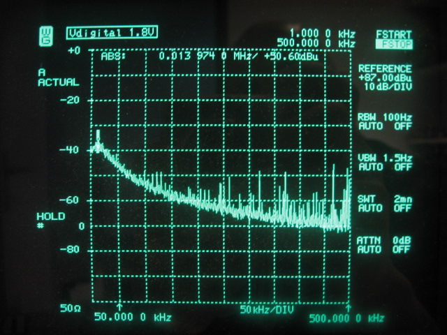
This picture is made possible thanks to the 40dB low frequency LNA, built as part of the PM-noise test set. The LNA is used to amplify the regulator noise to become completely visible down to the thermal noise floor, although the thermal floor is not quite reached with the LM317! The correction factor to convert the scale of this plot to dBμV/√Hz is -59.1dB. So the peak of +50.6dBμV corresponds to -8.5dBμV/√Hz, which is 376nV/√Hz. The plot bottoms out at 7.9nV/√Hz, which is still 25dB above the thermal noise floor. (446pV/√Hz in 50Ω) Notice the power supply pollution at the right side of the screen. This supports the recommendations by ADI to use separate voltage regulators on digital and analog supplies for demanding applications!
Although usually adequate, the LM317 regulator is less than perfect in the ultra-low-noise DDS application. I have checked a couple of other more current integrated LDO voltage regulators and I am sorry to report that they did not do better than the LM317 regulator. The Micrel MIC5205 is an exception, but only with a 10nF capacitor attached to its reference voltage bypass pin. Unfortunately, it is still not "low-noise" enough for the job at hand with the AD9910 DDS. It seems that the designers of modern LDO voltage regulators pay only little attention to the internal band-gap reference introduced noise, while the solution is so simple: an extra pin to properly de-couple the reference voltage with a big capacitor. Ironically this situation is much alike the latest ADI DDS chips that are missing that very same pin!
The "ideal" power supply in the DDS application should show a flat noise floor as close to the thermal noise floor as possible, also really close-in. The following picture shows the noise spectrum of the improved final version of the homemade "ultra-low-noise" regulator. The correction factor to convert the scale of this plot to dBμV/√Hz is -59.1dB:
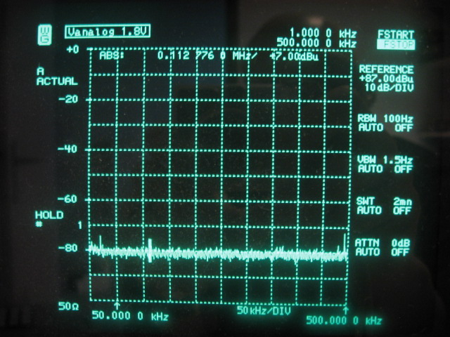
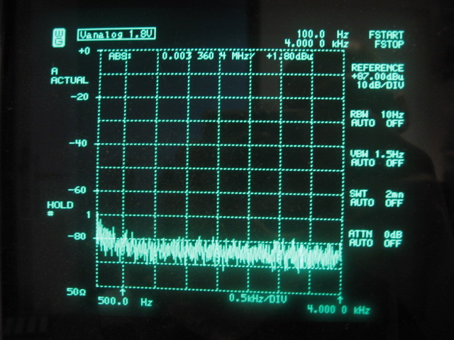
The noise floor at 7dbμV/√100Hz translates to 2.48nV/√Hz and exactly matches the specified noise input voltage of the opamp used as the error amplifier. (typically specified at 2.5nV/√Hz) This noise level (15dB above thermal noise) is maintained as close-in as 500Hz and at 100Hz it is only about 10dB stronger. This result is shown in the following picture which should be corrected with -54.1dB to convert the scale dBμV/√Hz:
The following photo depicts the final power supply PCB connected to the AD9910 evaluation board. To the left are the LM317 regulators to service the digital power rails. To the right are the components making up the ultra-low-noise regulators servicing the analog power rails:

With the ultra-low-noise regulators deployed, the final PM-noise result at 100MHz is as follows (scales are in dBc/Hz and KHz):
The "theoretical" residual PM-noise plot is taken from the AD9910 datasheet and has been measured at 98.6MHz. It almost completely overlaps the actually measured absolute PM-noise plot at 100MHz! At offsets < 300Hz the combination of increasing power supply noise and/or reference clock noise slightly raise the absolute noise plot. At offsets > 20KHz, there is also a slight disagreement between the two series. The goal however to produce absolute PM-noise results, very close to the published residual plots, has been reached at least at 100MHz!
Measuring at 14.3MHz
A LO working frequency of 100MHz is higher than we will ever need in the HF down conversion frontend. Therefore a final measurement at a much lower frequency is still needed to confirm that the AD9910 can do equally well when scaled down to a frequency closer to 16MHz (LO for 40M), where maintaining 120dB of dynamic range is our design goal. The digital divider that was intended to divide the clean Wenzel reference oscillator from 100MHz down to 16.67MHz cannot be used because of its built-in jitter. A dedicated low noise VCXO at 14.319MHz is constructed to enable this final PM-noise measurement. The following picture shows the VCXO and output amplifier in its metal box.
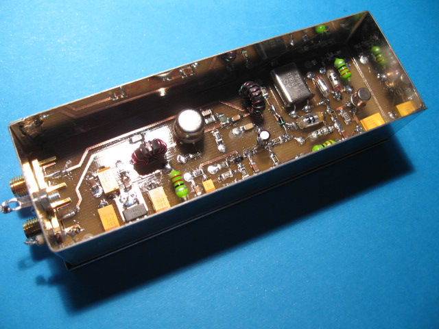
The VCXO produces a very clean +15dBm signal at 14.319MHz and can be pulled by about 40Hz to allow a quadrature lock with the DDS signal. The following graph shows the PM-noise result of this final exercise (scales are in dBc/Hz and KHz):
First of all, not all series have been normalized to 16MHz, but that accounts only for 0.5dB of false optimism, which is not too significant in this graph. The purple series represents the VCXO reference oscillator, which has been measured using the notch filter method. At least from 1KHz out it is well below the AD9910's residual noise plot, so it is of good enough quality to be used as the reference in this measurement.
Starting at an offset of about 600Hz, the measured PM-noise of the AD9910, the darker blue series, dives below the green baseline series! It also largely overlaps the red series, measured by ADI. Close-in, < 500Hz, the PM-noise of the VCXO reference is not good enough anymore and we are probably measuring the VCXO rather than the DDS. Further out, > 100KHz, the noise floor of the homebrew PM-noise test set is reached at -164,5dBc/Hz.
Both absolute PM-noise measurements of the DDS at 14.3MHz do not completely reach the theoretical limit presented by the residual phase noise from the datasheet, measured at 20.1MHz and scaled down to 16MHz, the light blue series. That goal is probably too ambitious at this very low noise level.
All in all, the 14.3MHz measurement can be called a success and is worth the effort. ADI's excellent PM-noise result with AD9910 proves to be reproducible. The frontends very tough phase noise requirement is already met at an offset of only 600Hz, which is still comfortably inside the SSB roofing filter! Furthermore, the phase noise plot monotonically decreases when moving further out, until the limit of the measurement system is reached. With this result, the frontends excellent IMD3DR will not be PNDR limited by the phase noise sidebands of the DDS-LO on 40M! The following picture shows the first 4KHz of PM-noise directly on the spectrum analyzer:
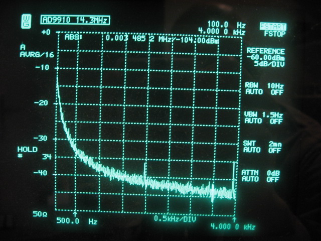
The correction factor to be used to turn the analyzers dBm scale into dBc/Hz for this picture is -54.8dB. Hence the PM-noise at 4KHz should be read as s -159dBc/Hz. There are also 2 very weak DDS spurs visible at around -140dBc. Note that spurs are discrete signals and are not affected like noise by the RBW of the analyzer. The following shot shows the first 100KHz of PM-noise on the analyzer:
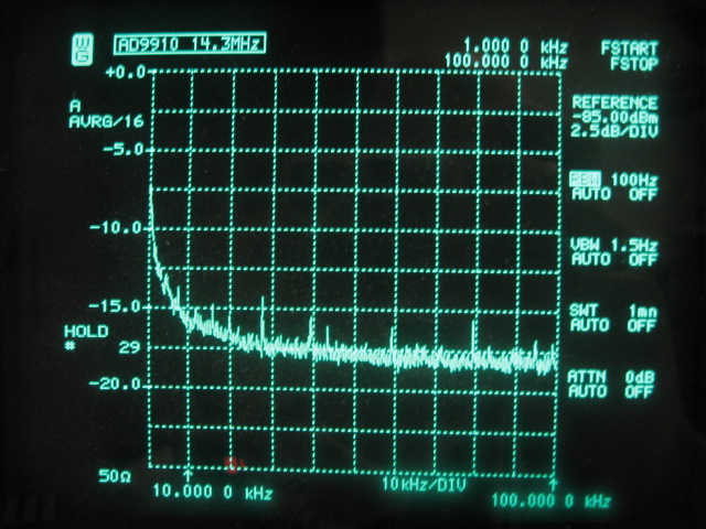
The correction factor to be used to turn the analyzers dBm scale into dBc/Hz for this picture is -59.8dB, which results in a noise floor at -164dBc/Hz. Also a couple of low energy spurs can be observed. The strongest spur at an offset of about 27KHz is around -140dBc.
More on DDS spurs
In order to show that DDS spurs can still become a bit of a nightmare, even with the AD9910, see the following picture:
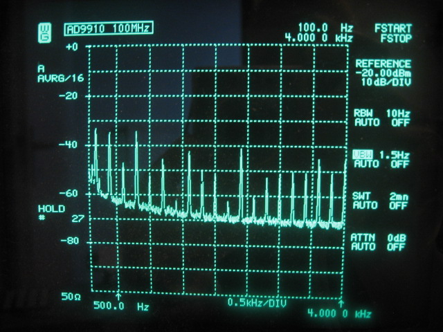
This is the PM-noise plot of the AD9910 at 100MHz. The correction factor to be used to turn the analyzers dBm scale into dBc/Hz for this picture is -54.8dB. This translates to a noise level of -146dBc/Hz at 4KHz. There are many spurs, separated by exactly 200Hz. The strongest spurs close-in are around -100dBc, which will not be visible on most general purpose spectrum analyzers, but with the extra 40dB amplification the PM-noise test set, they are!
Initially I thought that those spurs were 50Hz mains related. But I could not explain why in that case only multiples of 200Hz showed up. Furthermore, the spurs keep coming although with slowly decreasing level, but still visible at offsets of 200KHz and even further! That is quite unlike any 50Hz related mains pollution I have ever seen before, which usually dies out in the first couple of KHz!
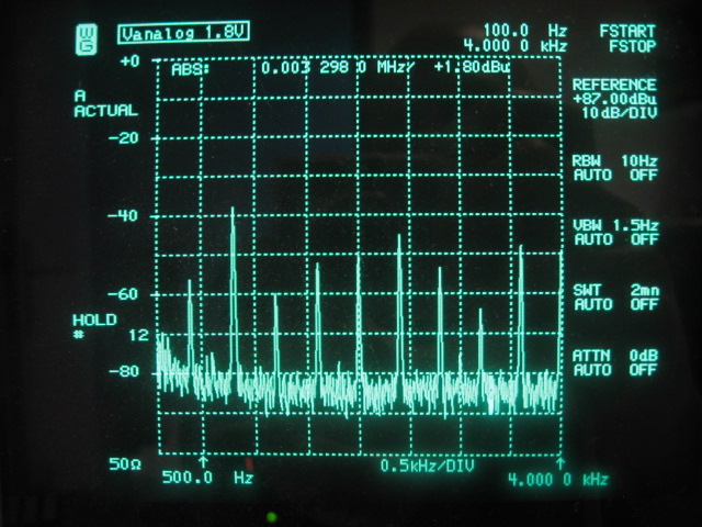
These spurs are caused by the unfortunate situation that 100MHz is a sub-harmonic of the 1GHz used by the DDS reference clock. The output frequency is actually set 40Hz above 100MHz in order to lock the PM-noise test to the DDS signal. The 10th harmonic of the output frequency gives a beat note of 400Hz. The exact mechanism why the spurs occur at 200Hz intervals rather than 400Hz is not clear to me, but it does seem to happen in the DAC circuitry. Inspection of the first 4KHz of the 1.8V analog power rail spectrum shows only spurs 400Hz apart.
So many spurs this close to each other can be seen as an elevated PM-noise floor in will seriously impair the otherwise excellent PNDR. This effect will only happen at sub-harmonics of the 1GHz reference clock and can be predicted easily. The following table shows a total of 11 sub-harmonic trouble spots inside the amateur bands given a 9MHz IF and a high side subtractive LO:
| Sub-harmonics related spurs inside amateur bands |
| Divisor |
LO (MHz) |
Rx (MHz) |
| 16 |
62.500000 |
53.500000 |
| 26 |
38.461538 |
29.461538 |
| 27 |
37.037037 |
28.037037 |
| 33 |
30.303030 |
21.303030 |
| 43 |
23.255814 |
14.255814 |
| 62 |
16.129032 |
7.129032 |
| 78 |
12.820513 |
3.820513 |
| 79 |
12.658228 |
3.658228 |
| 80 |
12.500000 |
3.500000 |
| 91 |
10.989011 |
1.989011 |
| 92 |
10.869565 |
1.869565 |
The issue with the sub-harmonic related spurs is not as worse as it looks. Most of the entries in the above table have quite high divisors and therefore the spurs are less strong.
1GHz Reference Clock
AD9910 Prototype Board
AD9910 and SSB-Noise
AD9910 and PM-Noise
Back to LO Design Choices
Back to the TOC
|