|
Signal Generators and Hybrid Combiner
I am using 2 completely separate and double shielded AD9951 DDS's (I0CG's design with 500MHz external clock). The DDS's produce about +8dBm output level with the ERA-1 MMIC. To reduce the 3rd order IMD products of the 2 DDS's together when connected to the hybrid combiner I have build 2-stage J310 grounded gate amplifiers that have a reverse isolation of better than -75dB up to 6M and around 4dB gain. This allows for IMD tests up to the +6dBm output level at the output of the combiner.
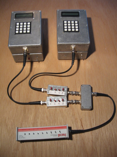
I am using a homemade hybrid combiner that isolates the input ports by more than 50dB on all bands except 160M where it gives only -48dB when the output is precisely terminated with 50 ohms. On 10M the isolation is -56dB peaking even to almost -70dB on 40MHz. The isolation provided by the combiner is much less unfortunately, as termination is not exactly 50 ohms resistive during real IP3 measurements. When connected to my homemade step attenuators the isolation is only -30dB decreasing to around -20dB on the higher bands.
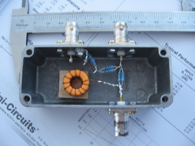
The following photo depicts my combiner. The toroid is a big "junkbox" type toroid with high permeability, probably manufactured originally for an rf-choke function.
Ten-Tec USA has kindly donated to me an ISOLINE-651 Combiner/Splitter. This combiner uses a very smart design to further improve port isolation. It features a trim potmeter that allows to dip the IMD by maximizing the port isolation, which is frequency and termination load dependent. Below 10MHz I have better results with my simple homebrew RLB-combiner, as the isoline's performance drops off considerably below 10MHz strangely enough for port 2 only. However above 10MHz I get slightly better results with the isoline combiner. Therefore I have started using the ISOLINE-651 on 20M and above for the IMD measurements made to the frontend together with the 10 band BPF-box. To get the best isolation, the adjustment is very sensitive indeed! A 10-turn potmeter would be needed to do that accurately. Furthermore the adjustment can only cancel out a resistive mismatch to 50 ohms on the output port. A reactive load cannot be fully compensated for!
I have attempted to measure the built-in IMD of this setup. My experimental receiver's front-end without BPF's in front has an IIP3 of around +40dBm or better. So by inserting 20db to 30dB of attenuation between the receiver and the combiner it should be possible to use this receiver to measure the output intercept point of the DDS's + combiner up to the +60dBm level with a reasonable level of confidence.
The following OIP3 observed of the DDS's and combiner described above with 20 kHz spacing:
| 2 x DDS + Combiner |
| Band |
Output level |
OIP3 |
IMD |
| dBm |
dBm |
dBc |
| 160 |
6,2 |
57,9 |
-103 |
| 80 |
6,3 |
56,3 |
-100 |
| 40 |
6,6 |
58,6 |
-104 |
| 30 |
6,6 |
57,1 |
-101 |
| 20 |
6,6 |
56,6 |
-100 |
| 17 |
6,5 |
53,5 |
-94 |
| 15 |
6,3 |
52,3 |
-92 |
| 12 |
6,1 |
51,4 |
-91 |
| 10 |
5,9 |
49,2 |
-87 |
| 6 |
3,0 |
45,7 |
-86 |
The listed OIP3 values are valid ONLY at the corresponding output level. Every dB of attenuation following the combiner must be subtracted from those values to reflect the actual OIP3 at that point. For this reason the attenuation to the desired output level to do the IP3 measurement should be done BEFORE the combiner. Each dB of attenuation before the combiner results in 2dBs of better isolation between the 2 DDS's. This might improve the listed IMD levels. Further more any IMD produced by the combiner's toroid core will be less if the levels there are kept to the minimum.
So this system is suitable to measure up to +50dBm on 160M-20M. On 17M-10M +45dBm is the limit. I have not determined the cause of the increased IMD at higher frequencies. It could be the combiner or the output amplifier or both.
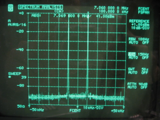
This picture (Wandel Goltermann SNA-62) confirms at least -90dBc IMD products with 1dBm input levels on 40M (OIP3>=+46dBm). Funny enough a few -80dBc or less AD9951 spurs are visible too! This is the best I can squeeze out of this instrument.
Back to the TOC
|