Introduction
The following overview is provided to me by Colin Horrabin, G3SBI, the inventor of the H-Mode mixer. Although more generally known for its use in down conversion receivers like in the CDG2000 and Picastar, it is perfectly possible to apply the H-Mode mixer circuit at higher frequencies in up-conversion mode. Colin designed and built a state of the art high dynamic range up conversion frontend with 2 H-Mode mixers to be used in conjunction with a modern DSP based back-end. I leave it to him to describe this front end in more detail and hopefully I will have an opportunity to build and test his design in the future!
Design Overview
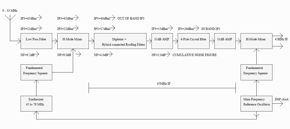
The mixer termination method used in the CDG2000 transceiver at 9MHz can also be used in an up-conversion receiver with a 45MHz IF with good results. Like the 9MHz IF two hybrid connected roofing filters are used to present a 50 ohm impedance to the mixer for close in signals. Like the CDG2000 to get a sensitive receiver without a preamplifier requires low loss crystal roofing filters at 45 MHz that also have a good in band and out of band IP3. A block diagram of a complete front end is shown here and this delivers an amplified signal down converted to a DSP IF system at 45KHz. This configuration will easily outperform the up conversion radios made by most people today and it is not over complicated.
The FSA3157 Switch has been investigated in detail by Martein Bakker PA3AKE as an H-Mode mixer and is well suited to be driven by a simple fundamental frequency squarer up to 75 MHz. It is a fast switching device and is a single pole double throw switch with break before make action so it does not need external logic to develop both the Q and not Q signal needed by the FST3125 had that been used.
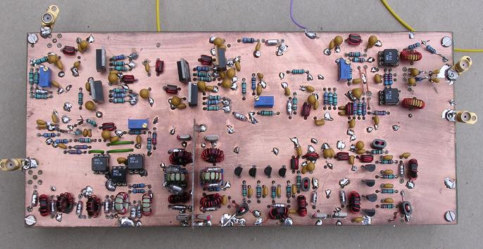
A complete front end has been built and tested and given to my friend John Thorpe the designer of the AOR 7030 receiver. John is working on the development of a new receiver for AOR UK. A block diagram of the experimental front end and photograph are shown in Fig1 and Fig2. Richard Hillier G4NAD and Mark Sumner G7KNY of AOR UK have provided components for evaluation and for use in the experimental front end both to G3SBI and also to PA3AKE. It has been possible to capitalize on the excellent work done by Martein on switches and transformers to further simplify the design of the front end.
Overall performance of the complete front end measured on 40M is:
IP3 at 15KHz 45dBm. In-band IP3 (within the 15KHz bandwidth of the roofing filter) is 22dBm at 1KHz spacing. Receiver noise figure is around 10dB without a preamplifier so the overall performance compares favorably with the CDG2000. The main difference is that the SSB bandwidth roofing filter used at 9MHz means that the CDG2000 will have a better closer in performance in IP3 and also lower local oscillator phase noise due to the lower frequency of the local oscillator. However John has come up with an interesting idea that should significantly improve the already excellent frequency synthesizer used on the AOR 7030.
The 4 pole fundamental mode crystal filters of 15KHz bandwidth at 45 MHz have an out of band IP3 at 15KHz of 40dBm and within their bandwidth 26dBm. Insertion loss is 1.8dB. A 7KHz bandwidth unit from the same manufacturer had an IP3 of 19dBm within the bandwidth and it was necessary to go out much further to get an out of band IP3 of 40dBm. So from a linearity point of view the wider filter was better. An additional four pole filter is used after the first amplifier so that image rejection techniques are not required at the second H-Mode mixer. The in band IP3 of the second filter sets the in band IP3 of the front end. The stop band of the filter system is over 100dB within 40KHz. It would have been possible to improve the in band IP3 (to 34 dBm at 1KHz) of the complete front end by not having a second filter and using image rejection circuitry.
The first amplifier at 45 MHz is a modified version of the 4X J310 amplifier used in the CDG2000 design. This amplifier has a gain in a 50 ohm system of 11dB. A noise figure of 1.5dB and an output IP3 of 40dBm. This is adequate performance to achieve the overall front end performance detailed above.
The second H mode mixer gives an impedance step up and push pull output at the 45KHz IF to the low frequency DSP system.
Hybrid Coupled Filters
Martein's recent release on the web of his measurement work on his production front end board does have implications for the up conversion front end. In particular his measurements of the CW roofing filter using the N2PK VNA are of real interest. One of the measurements showed the input impedance of a single CW filter. The impedance varied from zero to infinity and only gave a 50 Ohm match in the pass band. A mixer faced with such an impedance variation at the IF port would have its IP3 seriously degraded. A further measurement showed how the use of quadrature hybrid connected CW filters gave a near perfect 50 ohm match to the mixer. The use of Hybrid coupled filters to give a good close in match to a mixer was first covered in Bill Sabin's book 'Single sideband systems and circuits' which was published in 1987. However as far as I know I don't think the technique has ever been used commercially and it has been left to us radio amateurs to show that it is a simple and very effective way to terminate an H mode mixer.
A lumped circuit quadrature hybrid is a fairly simple device. It is just a bifilar winding on a torroid with two capacitors. If you want to know how to make one see Reed Fishers description in QST 'Twisted wire Quadrature Hybrid Directional Couplers' QST Vol 63 January 1978 pages 21-23. In fact the use of bonded bifilar wire gives better results particularly at near VHF. The hybrid used in the 45MHz up conversion front end was within 0.1 degrees of 90 degrees between 25 and 65 Mhz. If you want to obtain bonded bifilar wire or any other specialist wire a good source is 'The Scientific Wire Company' based in London (they are on the web). The other point that should be made about the lumped circuit Hybrid is that the capacitance between the bifilar wires has to be taken into account in the design. This capacitance is usually divided by two and subtracted from the value of each of the two capacitors that are part of the design. This approximation is suitable for a 9MHz hybrid but at 45 MHz you need a VNA to find the optimum values of capacitance. Once these have been found the design is repeatable.
Colin, G3SBI
AR7070 - Progress
AR7070 - Proto2 Measurements
Back to the TOC
|