|
2-Transfomer H-Mode mixer
Giancarlo Moda, I7SWX, has developed a variation of the H-Mode mixer that simplifies things by combining the 2 output transformers into a single transformer with 2 identical secondairy windings. Gian has been so kind to supply me with 2 prepared transformers. I have tested those with the FSA3157 switches + 74AC04 squarer in order be able to compare the results with all the others. It must be said that the FSA3157 mixer board layout being used is not optimal for the 2 transformer version of the mixer. Relatively long wiring is needed to plug the output transformer into this board, which might reduce performance.
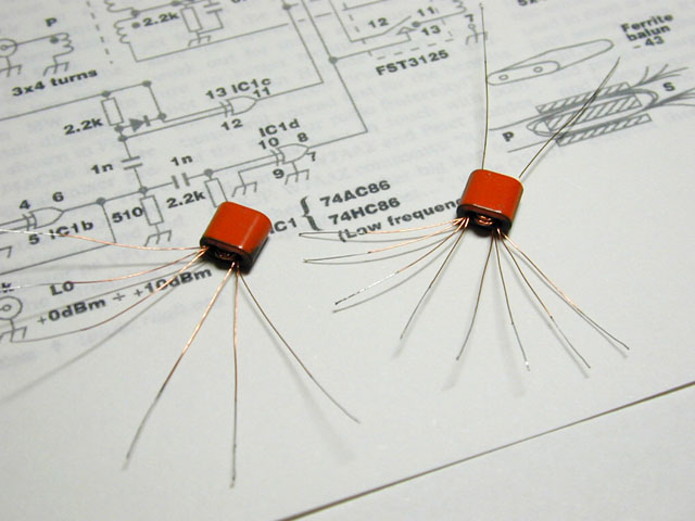
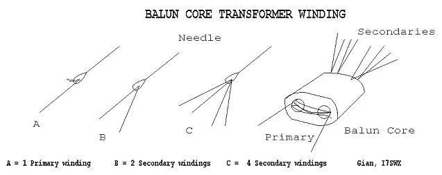
The transformers are wound on small BN43-2402 binocular cores. The primaries are 4 turns and the secondaries are 8 turns of 0.2mm enameled wire. The following picture shows in more detail how the transformers are to be constructed:
The single output transformer was prepared with an optional 4 turns extra on the primary side. This allowed for a configuration as a 1:4 or a 1:1 transformer. Note however that the input transformer is always a 1:4 transformer. The following table presents the results with Gian's transformers, both configured as 1:4 transformers:
| FSA3157 + BN43-2402 2x1:4 + 74AC04 |
Vdd = 7.0V, Vbias = 2.5V |
Best bias |
| Band |
BPF |
mixer |
MDS -dBm |
IF rej |
spur |
mixer IIP3 (dBm) @ 20KHz spacing |
Bias |
IIP3 |
| IL |
CL |
- |
+ |
|
avg |
-6 |
-3 |
0 |
+3 |
+5 |
|
0 |
| -dB |
-dB |
BPF |
BPF |
-dB |
dB |
dBm |
dBm |
dBm |
dBm |
dBm |
V |
dBm |
| 160 |
3,3 |
4,68 |
134,0 |
130,0 |
42,8 |
|
|
|
33,7 |
|
|
2,5 |
33,7 |
| 80 |
1,4 |
4,68 |
134,0 |
132,0 |
43,2 |
|
37,5 |
39,2 |
40,7 |
42,2 |
40,2 |
3,0 |
40,7 |
| 40 |
2,3 |
4,68 |
134,0 |
130,5 |
44,4 |
|
|
|
46,7 |
|
|
1,9 |
48,7 |
| 30 |
3,4 |
4,64 |
134,0 |
130,0 |
44,8 |
|
|
|
43,8 |
|
|
2,3 |
43,8 |
| 20 |
3,4 |
4,68 |
134,0 |
130,0 |
48,0 |
|
|
|
40,9 |
|
|
2,5 |
40,9 |
| 17 |
3,0 |
4,68 |
134,0 |
130,5 |
46,4 |
|
|
|
39,6 |
|
|
2,5 |
39,6 |
| 15 |
3,9 |
4,68 |
134,0 |
130,0 |
46,0 |
-7,0 |
|
|
39,4 |
|
|
2,5 |
39,4 |
| 12 |
3,7 |
4,72 |
134,0 |
130,0 |
41,2 |
|
|
|
38,1 |
|
|
2,5 |
38,1 |
| 10 |
2,3 |
4,68 |
134,0 |
131,0 |
37,6 |
|
|
|
36,3 |
|
|
2,7 |
36,3 |
| 6 |
|
5,84 |
131,0 |
|
50,0 |
|
|
|
36,7 |
|
|
2,9 |
36,7 |
| 4 |
|
6,80 |
131,0 |
|
27,6 |
|
|
|
33,4 |
|
|
2,4 |
33,4 |
Again like with the FT37-43 toroid homemade transformers the conversion loss is very low. This is certainly an area where homemade transformers excel. The low conversion loss is clearly showing in the MDS levels too except on 6M and 4M were spurs are raising the noise floor.
IP3 performance is comparable with the results obtained with TT4-1A except for 160M and 80M. Especially on 160M the IP3 is less good and the transformers seem to be the limitation there. IP3 is peaking on 40M. Performance is still good on 6M although spur levels are limiting the MDS!
These transformers show a noticeable sensitivity to the mixers bias point. Like observed with other 1:4 transformers this is most prevalent on 40M, where the IMD is clearly dipping rather steep at 1.9V bias.
With regard to the observed average spur levels on 15M, Gian's transformers perform really very good! At -7dB average, they are only second to ADTT1-1 (-9,3dB)! Probably having the two secondairies on one core gives a natural symmetry as it eliminates any core differences.
RF-IF isolation is good. With band specific adjustments it is possible to obtain values reaching -50dB on most bands.
The 2 transformer H-Mode mixer clearly is a very good alternative to the more expensive Minicircuits transformers. If IP3 performance is not the first priority and good spur rejection is important and if one is prepared to carefully duplicate Gian's transformers then this is a good alternative! A drawback could be that an adapted PCB layout for best performance is needed to keep good symmetry and short connections between the FSA3157 switches and the 2 transformers, like is possible for the stock transformers.
Next is a table with the results when the output transformer is configured as a 1:1 transformer. (The input transformer is still 1:4)
| FSA3157 + BN43-2402 1:4 + 1:1 + 74AC04 |
Vdd = 7.0V, Vbias = 2.5V |
Best bias |
| Band |
BPF |
mixer |
MDS -dBm |
IF rej |
spur |
mixer IIP3 (dBm) @ 20KHz spacing |
Bias |
IIP3 |
| IL |
CL |
- |
+ |
|
avg |
-6 |
-3 |
0 |
+3 |
+5 |
|
0 |
| -dB |
-dB |
BPF |
BPF |
-dB |
dB |
dBm |
dBm |
dBm |
dBm |
dBm |
V |
dBm |
| 160 |
3,3 |
6,60 |
132,0 |
128,5 |
49,6 |
|
|
|
40,9 |
|
|
1,3 |
41,4 |
| 80 |
1,4 |
6,60 |
132,0 |
130,0 |
50,4 |
|
43,2 |
44,0 |
45,0 |
46,2 |
47,0 |
3,0 |
46,0 |
| 40 |
2,3 |
6,56 |
132,0 |
129,5 |
51,6 |
|
|
|
44,9 |
|
|
3,0 |
46,4 |
| 30 |
3,4 |
6,44 |
132,0 |
128,0 |
52,8 |
|
|
|
44,0 |
|
|
3,0 |
45,3 |
| 20 |
3,4 |
6,48 |
132,0 |
128,0 |
55,2 |
|
|
|
46,2 |
|
|
3,0 |
47,2 |
| 17 |
3,0 |
6,44 |
132,0 |
127,0 |
52,8 |
|
|
|
45,8 |
|
|
2,6 |
46,3 |
| 15 |
3,9 |
6,44 |
132,0 |
127,5 |
66,4 |
-8,8 |
|
|
41,4 |
|
|
2,8 |
41,9 |
| 12 |
3,7 |
6,48 |
132,0 |
127,5 |
49,2 |
|
|
|
41,6 |
|
|
3,0 |
42,3 |
| 10 |
2,3 |
6,52 |
132,0 |
129,5 |
40,4 |
|
|
|
37,5 |
|
|
3,0 |
38,0 |
| 6 |
|
6,48 |
131,5 |
|
48,0 |
|
|
|
40,2 |
|
|
2,2 |
40,2 |
| 4 |
|
7,08 |
130,0 |
|
25,2 |
|
|
|
35,6 |
|
|
2,1 |
35,9 |
The IP3 results improve considerably when the output transformer is configured as 1:1. The configuration becomes a > +40dBm mixer except for a strange dip on 10M. Especially remarkable is the recovery of 160M!
The penalty however is found in the much increased conversion loss which takes a hit of almost an extra 2dB. The internal mismatch from 200 to 50 ohms is probably the cause of this effect.
Average spur level is better too by almost 2dB at -8.8dB. This might be explained by the increased conversion loss.
Worth noticing is that the bias point sensitivity has improved, much like with most 1:1 transformer configurations. Except for 160M, most bands are very unsensitive to the bias point.
RF-IF isolation is very good with a very steep null (-66dB) when adjusted on 15M. This value was not reproduceable on all bands though.
Changing the output transformer to 1:1 appears to be very good for the IMD performance. It is not quite clear how this works. The increased conversion loss however is a draw back with this configuration. The losses can be explained by a mismatch, therefore I have experimented with 4 additional turns on the input transformers primary turning that into 1:1 as well. The results were disappointing. More on that in a moment.
The remainder of this section describes the results obtained from a mixer board built by Gian himself. The board is double sided and is shown in the following picture:
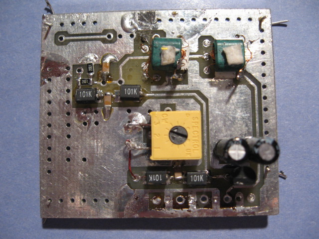
The top side is shown, with the 2 binocular transformers and the squarer symmetry pot. The squarer and the switches are located on the other side. The squarer is Gian's improved version of the classic 74AC86 squarer. The switches are an FST3125 clone by Pericom: PI5C3126. The switches are powered with 6V. This board has been developed for the 2 transformer mixer configuration.
The following table shows the results when both transformers are configured as 1:4 transformers:
| PI5C3126 + BN43-2402 2x1:4 + 74AC86 |
Vdd = 6.0V, Vbias = 3V |
Best bias |
| Band |
BPF |
mixer |
MDS -dBm |
IF rej |
spur |
mixer IIP3 (dBm) @ 20KHz spacing |
Bias |
IIP3 |
| IL |
CL |
- |
+ |
|
avg |
-6 |
-3 |
0 |
+3 |
+5 |
|
0 |
| -dB |
-dB |
BPF |
BPF |
-dB |
dB |
dBm |
dBm |
dBm |
dBm |
dBm |
V |
dBm |
| 160 |
3,3 |
4,92 |
133,0 |
129,0 |
39,6 |
|
|
|
33,7 |
|
|
3,0 |
33,7 |
| 80 |
1,4 |
4,90 |
133,5 |
132,0 |
39,6 |
|
37,0 |
39,2 |
40,7 |
40,2 |
37,7 |
3,0 |
40,7 |
| 40 |
2,3 |
4,96 |
133,5 |
131,0 |
40,8 |
|
|
|
41,2 |
|
|
1,8 |
43,9 |
| 30 |
3,4 |
4,96 |
133,5 |
129,5 |
42,0 |
|
|
|
39,5 |
|
|
1,8 |
42,3 |
| 20 |
3,4 |
4,96 |
133,5 |
129,5 |
44,8 |
|
|
|
38,4 |
|
|
1,6 |
40,7 |
| 17 |
3,0 |
4,92 |
133,5 |
129,5 |
45,6 |
|
|
|
38,1 |
|
|
1,7 |
39,8 |
| 15 |
3,9 |
4,92 |
133,5 |
128,0 |
55,6 |
6,2 |
|
|
37,6 |
|
|
1,7 |
38,9 |
| 12 |
3,7 |
4,92 |
133,0 |
128,5 |
45,6 |
|
|
|
37,3 |
|
|
1,7 |
38,6 |
| 10 |
2,3 |
4,92 |
132,5 |
127,0 |
54,8 |
|
|
|
35,8 |
|
|
1,8 |
36,3 |
| 6 |
|
6,00 |
123,0 |
|
37,6 |
|
|
|
36,7 |
|
|
3,0 |
36,7 |
| 4 |
|
7,08 |
118,0 |
|
27,2 |
|
|
|
30,6 |
|
|
3,0 |
30,6 |
The most striking result is that the average spur level is rather strong at 6.2dB, which is 13dB stronger than with the FSA3157 version of the 2T mixer. This is in line with the test with ADTT1-1 and FSAV332. That combination did not do well with spurs either while ADTT1-1 and FSA3157 did do very well. It looks like SPST switches like FST3125 and FSAV332 are not the best choice when it comes to maintaining excellent mixer symmetry way into VHF to cancel out the DDS spurs.
The adjustment of the RF-IF isolation with Gian's 74AC86 squarer is very good. With band specific adjustments it was possible to obtain over 55dB of isolation on most bands. The results shown in the table are with a mark/space ratio for best RF-IF isolation on 15M.
Next is the configuration where the input transformer is configured as a 1:4 transformer and the output transformer is configured as a 1:1 transformer:
| PI5C3126 + BN43-2402 1:4 + 1:1 74AC86 |
Vdd = 6.0V, Vbias = 3V |
Best bias |
| Band |
BPF |
mixer |
MDS -dBm |
IF rej |
spur |
mixer IIP3 (dBm) @ 20KHz spacing |
Bias |
IIP3 |
| IL |
CL |
- |
+ |
|
avg |
-6 |
-3 |
0 |
+3 |
+5 |
|
0 |
| -dB |
-dB |
BPF |
BPF |
-dB |
dB |
dBm |
dBm |
dBm |
dBm |
dBm |
V |
dBm |
| 160 |
3,3 |
6,80 |
132,0 |
128,5 |
44,0 |
|
|
|
41,2 |
|
|
3,0 |
41,2 |
| 80 |
1,4 |
6,80 |
132,0 |
131,0 |
44,0 |
|
44,0 |
45,5 |
47,0 |
47,5 |
46,7 |
3,0 |
47,0 |
| 40 |
2,3 |
6,72 |
132,0 |
129,5 |
44,4 |
|
|
|
49,4 |
|
|
3,0 |
49,4 |
| 30 |
3,4 |
6,60 |
131,5 |
127,5 |
45,6 |
|
|
|
47,5 |
|
|
3,0 |
47,5 |
| 20 |
3,4 |
6,65 |
131,5 |
127,0 |
47,2 |
|
|
|
45,7 |
|
|
1,7 |
46,9 |
| 17 |
3,0 |
6,40 |
131,5 |
127,0 |
47,2 |
|
|
|
43,3 |
|
|
1,3 |
46,6 |
| 15 |
3,9 |
6,36 |
131,5 |
126,0 |
65,2 |
3,9 |
|
|
44,4 |
|
|
3,0 |
44,4 |
| 12 |
3,7 |
6,32 |
131,5 |
127,0 |
47,2 |
|
|
|
42,6 |
|
|
3,0 |
42,6 |
| 10 |
2,3 |
6,36 |
131,5 |
126,5 |
52,8 |
|
|
|
41,0 |
|
|
3,0 |
41,0 |
| 6 |
|
6,04 |
131,5 |
|
47,6 |
|
|
|
40,2 |
|
|
3,0 |
40,2 |
| 4 |
|
6,40 |
121,0 |
|
26,8 |
|
|
|
35,4 |
|
|
1,1 |
37,4 |
Again IP3 gets a big boost with this change to the output transformer. This time it works even better than with the FSA3157 switches! Maybe the more optimal PCB layout helps. Obviously, the Pericom version of the 3125 bus-switches is capable of very high IP3 when used in combination with the right transformers. From its datasheet one can see that Ton/Toff switching times are symmetrical with respect to the min and max times, although no specification is made for the 'typical' case. The min time is also better than the original Fairchild bus-switch with only 0.5nS, max times are similar to Fairchild though.
The RF-IF isolation improved a lot too. With band specific adjustments some bands could be tuned to over 60dB, sometimes 70dB of isolation. 160M did even an incredible 80dB! The values shown are for an adjustment to 15M.
Again the penalty however is found in the much increased conversion loss which takes a hit of almost an extra 2dB. The internal mismatch from 200 to 50 ohms is probably the cause of this effect.
The average spur levels decreased with about the amount that the conversion loss increased.
Next is the configuration where both the input transformer and the output transformer are configured as 1:1 transformers:
| PI5C3126 + BN43-2402 2x1:1 74AC86 |
Vdd = 6.0V, Vbias = 3V |
Best bias |
| Band |
BPF |
mixer |
MDS -dBm |
IF rej |
spur |
mixer IIP3 (dBm) @ 20KHz spacing |
Bias |
IIP3 |
| IL |
CL |
- |
+ |
|
avg |
-6 |
-3 |
0 |
+3 |
+5 |
|
0 |
| -dB |
-dB |
BPF |
BPF |
-dB |
dB |
dBm |
dBm |
dBm |
dBm |
dBm |
V |
dBm |
| 160 |
3,3 |
5,32 |
133,0 |
129,5 |
41,2 |
|
|
|
39,9 |
|
|
3,0 |
39,9 |
| 80 |
1,4 |
5,36 |
133,0 |
131,0 |
41,6 |
|
44,7 |
46,2 |
46,5 |
43,5 |
39,2 |
2,4 |
47,5 |
| 40 |
2,3 |
5,48 |
133,0 |
130,0 |
42,0 |
|
|
|
45,4 |
|
|
1,7 |
47,2 |
| 30 |
3,4 |
5,52 |
133,0 |
129,0 |
44,0 |
|
|
|
44,0 |
|
|
1,6 |
46,5 |
| 20 |
3,4 |
5,88 |
132,5 |
127,5 |
44,4 |
|
|
|
42,9 |
|
|
3,0 |
42,9 |
| 17 |
3,0 |
6,04 |
132,5 |
128,0 |
42,4 |
|
|
|
39,1 |
|
|
3,0 |
39,1 |
| 15 |
3,9 |
6,08 |
132,0 |
127,5 |
48,8 |
2,3 |
|
|
38,9 |
|
|
3,0 |
38,9 |
| 12 |
3,7 |
6,20 |
132,0 |
127,5 |
54,0 |
|
|
|
42,1 |
|
|
3,0 |
42,1 |
| 10 |
2,3 |
6,72 |
131,5 |
129,0 |
46,8 |
|
|
|
41,3 |
|
|
3,0 |
41,3 |
| 6 |
|
6,04 |
130,0 |
|
36,0 |
|
|
|
32,2 |
|
|
3,0 |
32,2 |
| 4 |
|
6,04 |
126,0 |
|
34,4 |
|
|
|
30,1 |
|
|
3,0 |
30,1 |
My expectations were high for the 2T h-mode mixer with 1:1 transformers. The conversion loss should improve and hopefully the good IP3 results would remain. This did not turn out to be so easy.
Conversion loss did improve indeed, but gets progressively worse on the higher bands, especially 10M.
IP3 results are still good, but are less than with the 'mismatched' mixer. Especially worth noticing is that this configuration is not able to maintain IP3 at higher input levels.
RF-IF isolation reduced, although values around 50dB are possible with band specific adjustments.
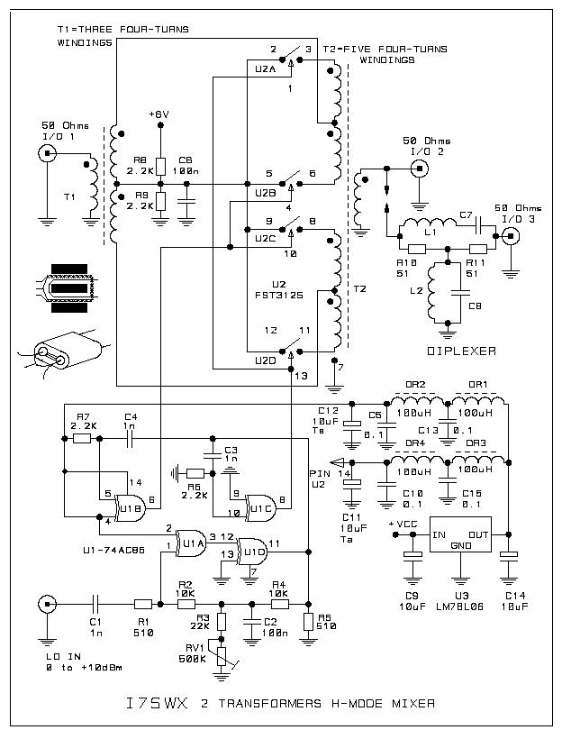
The following picture shows the schematic of the tested I7SWX 2T mixer board. When compared with the original G3SBI 3T mixer it can be seen that the output transformer primaries of 2 transformers are collapsed into a single primary. Consequently the 180 phase shift is moved into the secondaries by swapping one secondairy. The diplexer drawn near the IF output is not part of the assembly. The 74AC86 squarer circuit is similar to the 74AC04 squarer used in my FSA3157 tests. Gian's squarer however uses an extra inverter to provide both Q and !Q required to drive the SPST switches.
Back to H-Mode mixer Introduction
Back to the TOC
|