|
Measurements by John Thorpe on the AR7070 HF Receiver Production Prototype, 14-10-2010
Martein and I have both been involved in the research that made this radio possible. In my opinion it will prove to be the best up conversion HF radio of all time.
The AR7070 has been designed by my friend John Thorpe the designer of the highly acclaimed AR7030 HF receiver and also the designer of the 'HF' series of receivers made in Matlock by Lowe Electronics in the late 1980s and early 1990s. The AR7070 is an up conversion receiver that uses the techniques of the receive section of the CDG2000 transceiver that Martein improved upon to make his 'holy grail' receiver with a 9MHz IF. Like the CDG2000 receiver the AR7070 is sensitive enough not to require a preamplifier before its first H mode mixer.
These receivers are only as good as the linearity of their crystal roofing filters and Martein was able to build a 4 pole 2.5 KHz bandwidth roofing filter at 9MHz with 1dB insertion loss and IP3 in band of 35dBm and out of band of 56dBm. These results were possible due to the outstanding quality of the 9MHz crystals supplied to him by the German firm Quarz Technik. Martein also designed a 500Hz wide filter using the same crystals and found that the in band IP3 was degraded to 25 dBm. He had shown conclusively that for a given quality of quartz in band IP3 of the filter degraded at roughly 6 dB per octave reduction in design bandwidth. So in an up conversion receiver you want a wide roofing filter that has good in-band linearity not a narrow one. However if the following circuitry after a wide roofing filter is not linear enough before the 24 Bit ADC the full potential performance of the 24 Bit DSP system will not be realised. There is a message here for the designers of Japanese HF radios. In the case of Martein's down conversion receiver with a 9MHz IF the H mode mixer is the limitation in receiver IP3 performance due to the fabulous 56 dBm out of band IP3 of his crystal filter.
The roofing filters in the AR7070 have a 15KHz bandwidth centred on 45 MHz. They were supplied by the British firm TFC (Total Frequency Control). The in band IP3 is 26 dBm and out of band at 20 KHz tone spacing is 38 dBm. After the first H mode mixer two 2 pole filters are connected via hybrids to terminate the mixer. These filters also protect the first IF amplifier from strong out of band signals. The first IF amplifier drives a 4 pole roofing filter and it is this filter that sets the in band IP3 of the radio at the antenna (20 dBm). The 6 poles of filtering in the 45 MHz signal path means that the image at the second H mode mixer is over 100 dB down therefore image rejection circuitry is not required at the second mixer. The circuitry after the roofing filters including the 45 KHz IF is highly linear and does not compromise the performance of the 24Bit audio ADC. At 200Hz test tone spacing the radio still has an IP3 of 19dBm giving a IP3 dynamic range of 97dB in an SSB bandwidth. These fabulous results are due to advanced fixed point DSP software that is not compromised by poor linearity in the analog signal path to the 24 Bit audio ADC. At an early stage of the development of the AR7070s front end circuitry IP3 measurements were made on a 7.5KHz wide roofing filter. In band IP3 followed Martein's results and was 7dB worse than the 15 KHz bandwidth unit. Also unlike Martein's 9 MHz CW filter the 7.5 KHz bandwidth filter had a worse out of band IP3 performance.
To illustrate a particular point: The review by Peter Hart G3SJX of the Yaesu FTDX5000 in the June 2010 RadCom measured close in IP3 on the 7MHz band using the down conversion receiver. He did these tests with different roofing filter bandwidths. The test using a 15 KHz wide filter clearly showed that the IP3 within the roofing filter bandwidth was only -8.5 dBm. With the receiver noise figure being around 20 dB this gives a close in IP3 dynamic range of only 77dB compared to the AR7070s 19 dBm and 97 dB dynamic range in an SSB bandwidth. Clearly in the FTDX5000 the signal path after the filter is not linear enough and that shows in the technical measurement made by Peter. However the 97dBm close in IP3 dynamic range of the AR7070 is limited by reciprocal mixing to 82 dB which is still better than the FTDX5000s down conversion receiver at 77 dB. The close in phase noise of the local oscillator in the FTDX5000s down conversion receiver is superior to the AR7070 which after all is an up conversion radio. Therefore the dynamic range of the receiver in the FTDX5000 could be increased by improving the linearity of the signal path following the roofing filters.
Most reviewers of amateur radio equipment do not quote IP2 linearity. This is around 100dB for the AR7070. This measurement is important for radios that do not use sub octave filters before the mixer. The IP2 for the AR7070 is similar to that in the AR7030 receiver and it has not surfaced in practice as a big issue. Obviously some sort of pre selector could improve IP2 significantly on the AR7070. It also is a measurement that should be made on the latest SDRs that use direct sampling at the antenna with 100MHz 16 Bit ADCs. To illustrate the effects of IP2: If you are listening on 14.3 MHz and there are strong stations at 7.1 and 7.2 MHz the mixer would generate IP2 at 14.3 MHz.
Apart from the linearity of the signal path an important parameter in a superhet radio is the effects of reciprocal mixing due to local oscillator phase noise sidebands. The AR7070 still uses a PLL/DDS solution for the frequency synthesizer using a double tank VCO. This is similar to that used in the AR7030 receiver but of improved performance. Although the use of a DDS chip directly as the local oscillator was considered. As things stand at the moment suppression of spurs was deemed not good enough for an up conversion radio. Martein also identified an AM noise issue with the latest 14 bit DAC DDS chips from Analog Devices. The investigation of this is covered on this web site.
Perhaps surprisingly Martein and I are on good terms with the guys in the high speed DDS group in North Carolina. Their latest DDS chip will be a 12 bit DAC 4GHz clocking device. However they are interested in doing a 16 bit part and when this is available it may prove suitable for use in up conversion radios and give much better close in phase noise that would increase very close in receiver dynamic range for a signal path design like the AR7070.
The phase noise on the local oscillator for the AR7070 is excellent for an up conversion radio and in fact is better than a state of the art commercial down conversion receiver. However, being a perfectionist in my opinion it could be further improved in the transition region (1Khz to 8KHz from carrier) with a better phase detector. The present phase detector has some useful features but uses a band gap voltage reference and these have a very characteristic noise profile with a plateau that extends outward to about 200KHz. Martein has done quite a bit with noise plateau�s in the AD9910 investigation which is covered elsewhere on this web site. Non bypassed band gap voltage references appear to be bad news for anything involved in state of the art local oscillators. The present phase detector uses a band gap reference un-bypassed and it looks like the limit within the PLL bandwidth is -116dBc/Hz, which is still an excellent figure at 200Hz off carrier. I have mentioned my suspicions on this to John Thorpe but the only way to be certain about this is to obtain an internal circuit of the phase detector chip so we can see how the band gap reference voltage affects the charge pump. An investigation of this effect is worthwhile for the knowledge gained. However there are no plans to alter circuitry in the radio due to the already excellent overall phase noise profile of the AR7070s present local oscillator.
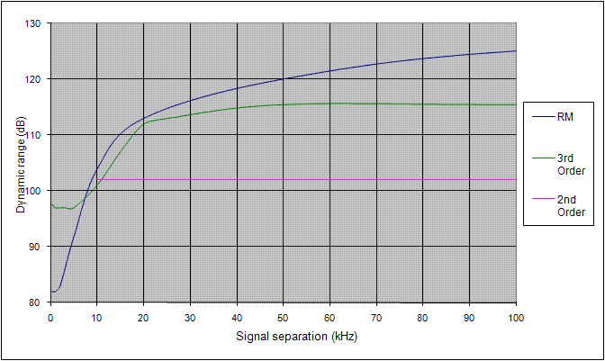
The technical measurements presented here are first rate for an up conversion radio. They show why this radio has such a fabulous on air performance. The dynamic range graph showing the relationship of reciprocal mixing with IP2 and IP3 clearly shows that the AR7070 is a high performance up conversion radio.
So far there has only been a select few that have been able listen to the radio at their QTH and compare it with their own receivers. John must have done a good job with the DSP software because everyone has been very enthusiastic about the AR7070s on air performance.
As you know Martein's web site has been dedicated to information on how to make state of the art receivers and that is why this information is presented here. The plan is to build ten production prototypes in the near future but this has been complicated by the global recession and as a result some components are on extended lead times. When the full story behind the development of this receiver is written up for Radcom you will see that some of the important analog circuitry used in the receiver has been due to the ideas of radio amateurs on both sides of the pond.
Colin, G3SBI
Below is presented extensive measurement data provided to me by John Thorpe regarding key aspects of the AR7070 HF receiver. All are directly linked to the performance of its frontend. It shows that the AR7070 is a superb receiver and I have not seen anything like it so far in the HF up-conversion arena, while the up-conversion architecture is very popular and even dominating commercially for over 25 years now!
My H-mode mixer experiments have concentrated mainly on the deployment of the mixer in a 9MHz down-conversion architecture, but the 6M and 4M test results available elsewhere on this website did show already that the mixer is performing also into low VHF. Now John's measurements confirm this and also show that the H-Mode mixer is capable of good performance at as low as 10KHz! John added a couple of refinements to the version of the H-Mode mixer used in the AR7070 frontend, which have pushed the envelope even further. I am curious to see if these refinements will be helpful in the down-conversion scenario also. So there is more for me to do with the mixer in the future.
I hope I will soon have an opportunity to listen to the AR7070 on air!
Martein, PA3AKE
Sensitivity and Spurious Rejection
| AR7070 proto2 Sensitivity and Spurious Rejection |
| Freq |
Sensitivity |
Sensitivity for 10dB S/N |
Spurious Rejection |
| Receive |
MDS 2.4KHz |
Noise Figure |
2.4KHz |
500Hz |
30%AM 6KHz |
1st IF Image (f+2*IF) |
45MHz (IF) |
22.5MHz (IF/2)* |
15MHz (IF/3)* |
2nd IF Image(f+86KHz)** |
| (MHz) |
(dBm) |
(dB) |
(uV) |
(uV) |
(uV) |
(dB) |
(dB) |
(dB) |
(dB) |
(dB) |
| 0.01 |
-120,3 |
19,7 |
0,68 |
0,31 |
3,55 |
|
|
|
|
|
| 0,02 |
-125,9 |
14,1 |
0,36 |
0,16 |
1,86 |
|
|
|
|
|
| 0,05 |
-127,5 |
12,5 |
0,30 |
0,13 |
1,55 |
|
|
|
|
|
| 0,1 |
-127,5 |
12,5 |
0,30 |
0,13 |
1,55 |
|
|
|
|
|
| 0,5 |
-127,5 |
12,5 |
0,30 |
0,13 |
1,55 |
|
|
|
|
|
| 1,1 |
-127,1 |
12,9 |
0,31 |
0,14 |
1,62 |
114 |
95 |
142 |
|
|
| 2,1 |
-127,7 |
12,3 |
0,29 |
0,13 |
1,51 |
102 |
101 |
102 |
118 |
|
| 3,1 |
-127,8 |
12,2 |
0,29 |
0,13 |
1,50 |
|
|
|
|
|
| 4,1 |
-127,5 |
12,5 |
0,30 |
0,13 |
1,55 |
105 |
102 |
102 |
119 |
|
| 7,1 |
-127,4 |
12,6 |
0,30 |
0,13 |
1,57 |
114 |
109 |
100 |
119 |
|
| 10,1 |
-127,4 |
12,6 |
0,30 |
0,13 |
1,57 |
|
|
|
|
|
| 14,1 |
-127,2 |
12,8 |
0,31 |
0,14 |
1,60 |
115 |
103 |
108 |
119 |
115 |
| 18,1 |
-127,7 |
12,3 |
0,29 |
0,13 |
1,51 |
|
|
|
|
|
| 21,1 |
-127,6 |
12,4 |
0,30 |
0,13 |
1,53 |
112 |
101 |
102 |
118 |
|
| 24,1 |
-127,9 |
12,1 |
0,29 |
0,13 |
1,48 |
|
|
|
|
|
| 28,1 |
-128,0 |
12,0 |
0,28 |
0,13 |
1,46 |
115 |
98 |
104 |
119 |
|
| 29,9 |
-127,7 |
12,3 |
0,29 |
0,13 |
1,51 |
116 |
98 |
102 |
119 |
|
* 22.5MHz and 15MHz rejection measured relative to a wanted signal at the level of the noise floor (-127dBm).
** The 2nd IF image is invarient with receive frequency.
Reciprocal Mixing
| AR7070 proto2 Reciprocal Mixing in 2.4KHz BW |
| Freq |
Test signal for 3dB noise |
LO Phase Noise |
Dynamic Range |
| Offset |
7.1MHz |
14.1MHz |
28.1MHz |
7.1MHz |
14.1MHz |
28.1MHz |
7.1MHz |
14.1MHz |
28.1MHz |
| (KHz) |
(dBm) |
(dBm) |
(dBm) |
(dBc/Hz) |
(dBc/Hz) |
(dBc/Hz) |
(dB) |
(dB) |
(dB) |
| 0.2 * |
-45 |
-47 |
-52 |
-116 |
-114 |
-109 |
82 |
80 |
75 |
| 0.5 * |
-45 |
-47 |
-52 |
-116 |
-114 |
-109 |
82 |
80 |
75 |
| 1 * |
-45 |
-47 |
-52 |
-116 |
-114 |
-109 |
82 |
80 |
75 |
| 2 |
-44 |
-46 |
-52 |
-117 |
-115 |
-109 |
83 |
81 |
75 |
| 5 |
-35 |
-37 |
-44 |
-126 |
-124 |
-117 |
92 |
90 |
83 |
| 10 |
-23 |
-26 |
-32 |
-138 |
-135 |
-129 |
104 |
101 |
95 |
| 20 |
-14 |
-17 |
-23 |
-147 |
-144 |
-138 |
113 |
110 |
104 |
| 50 |
-7 |
-10 |
-11 |
-154 |
-151 |
-150 |
120 |
117 |
116 |
| 100 ** |
-2 |
|
|
-159 |
|
|
125 |
|
|
| 200 ** |
+1 |
|
|
-162 |
|
|
128 |
|
|
| 500 ** |
+3 |
|
|
-164 |
|
|
130 |
|
|
* Filter PBS adjusted to remove test signal.
** Measured at 9Mhz with a low noise signal source.
3rd order IMD
| AR7070 proto2 3rd order IMD, 50KHz separated 2-tones in 2.4KHz BW. |
| Freq |
Test signal for IMD3 at MDS level |
IIP3 |
Dynamic Range |
| Receive |
Low |
High |
Avg |
Low |
High |
Avg |
Low |
High |
Avg |
| (MHz) |
(dBm) |
(dBm) |
(dBm) |
(dBm) |
(dBm) |
(dBm) |
(dB) |
(dB) |
(dB) |
| 1.6 |
-15,0 |
-15,0 |
-15,0 |
-41,0 |
-41,0 |
-41,0 |
112,0 |
112,0 |
112,0 |
| 2.1 |
-14,0 |
-14,0 |
-14,0 |
42,5 |
42,5 |
42,5 |
113,0 |
113,0 |
113,0 |
| 4.1 |
-11,0 |
-11,5 |
-11,3 |
47,0 |
46,3 |
46,6 |
116,0 |
115,5 |
115,8 |
| 7.1 |
-11,5 |
-12,0 |
-11,8 |
46,3 |
45,5 |
45,9 |
115,5 |
115,0 |
115,3 |
| 10.1 |
-12,5 |
-13,0 |
-12,8 |
44,8 |
44,0 |
44,4 |
114,5 |
114,0 |
114,3 |
| 14.1 |
-11,0 |
-11,0 |
-11,0 |
47,0 |
47,0 |
47,0 |
116,0 |
116,0 |
116,0 |
| 18.1 |
-12,0 |
-12,0 |
-12,0 |
45,5 |
45,5 |
45,5 |
115,0 |
115,0 |
115,0 |
| 21.1 |
-12,0 |
-12,0 |
-12,0 |
45,5 |
45,5 |
45,5 |
115,0 |
115,0 |
115,0 |
| 24.1 |
-12,0 |
-11,5 |
-11,8 |
45,5 |
46,3 |
45,9 |
115,0 |
115,5 |
115,3 |
| 28.1 |
-11,5 |
-11,0 |
-11,3 |
46,3 |
47,0 |
46,6 |
115,5 |
116,0 |
115,8 |
| 29.9 |
-13,0 |
-12,5 |
-12,8 |
44,0 |
44,8 |
44,4 |
114,0 |
114,5 |
114,3 |
| AR7070 proto2 3rd order IMD at 7.1MHz in 2.4KHz BW |
| Freq |
Test signal for IMD3 at MDS level |
IIP3 |
Dynamic Range |
| Offset |
Low |
High |
Avg |
Low |
High |
Avg |
Low |
High |
Avg |
| (KHz) |
(dBm) |
(dBm) |
(dBm) |
(dBm) |
(dBm) |
(dBm) |
(dB) |
(dB) |
(dB) |
| 0.1 * |
-30,0 |
-29,5 |
-29,8 |
18,5 |
19,3 |
18,9 |
97,0 |
97,5 |
97,3 |
| 0.5 * |
-30,0 |
-29,0 |
-29,5 |
18,5 |
20,0 |
19,3 |
97,0 |
97,5 |
97,3 |
| 1 * |
-31,0 |
-29,0 |
-30,0 |
17,0 |
20,0 |
18,5 |
96,0 |
98,0 |
97,0 |
| 3 |
-32,0 |
-29,0 |
-30,5 |
15,5 |
20,0 |
17,8 |
95,0 |
98,0 |
96,5 |
| 5 |
-31,0 |
-30,0 |
-30,5 |
17,0 |
18,5 |
17,8 |
96,0 |
97,0 |
96,5 |
| 10 |
-26,0 |
-26,5 |
-26,3 |
24,5 |
23,8 |
24,1 |
101,0 |
100,5 |
100,8 |
| 15 |
-21,0 |
-18,5 |
-19,8 |
32,0 |
35,8 |
33,9 |
106,0 |
108,5 |
107,3 |
| 20 |
-18,0 |
-13,0 |
-15,5 |
36,5 |
44,0 |
40,3 |
109,0 |
114,0 |
111,5 |
| 25 |
-15,0 |
-13,0 |
-14,0 |
41,0 |
44,0 |
42,5 |
112,0 |
114,0 |
113,0 |
| 50 |
-11,5 |
-12,0 |
-11,8 |
46,3 |
45,5 |
45,9 |
115,5 |
115,0 |
115,3 |
* Measured using narrower filter (filter bandwidth does not affect result).
2nd order IMD
| AR7070 proto2 2nd order IMD in 2.4KHz BW |
| Freq |
Test signals |
Signal level for IMD2 at MDS level |
IIP2 |
Dynamic Range |
| (MHz) |
(MHz) |
(MHz) |
(dBm) |
(dBm) |
(dB) |
| 1.6 |
2,0 |
3,6 |
-24 |
79 |
103 |
| 1.6 |
6,0 |
7,6 |
-14 * |
99 |
113 |
| 2.6 |
1,0 |
1,6 |
-26 |
75 |
101 |
| 7.1 |
3,5 |
3,6 |
-23 |
81 |
104 |
| 7.1 |
3,5 |
10,6 |
-20 |
87 |
107 |
| 7.1 |
9,5 |
16,6 |
-12 |
103 |
115 |
| 7.1 |
15,5 |
22,6 |
-23 |
81 |
104 |
| 7.1 |
21,5 |
28,6 |
-26 |
75 |
101 |
| 14.1 |
6,5 |
7,6 |
-21 |
85 |
106 |
| 14.1 |
4,5 |
9,6 |
-23 |
81 |
104 |
| 14.1 |
4,5 |
18,6 |
-21 |
85 |
106 |
| 14.1 |
9,5 |
23,6 |
-23 |
81 |
104 |
| 14.1 |
14,5 |
28,6 |
-19 |
89 |
108 |
| 21.1 |
10,5 |
10,6 |
-22 |
83 |
105 |
| 21.1 |
7,5 |
13,6 |
-22 |
83 |
105 |
| 21.1 |
4,5 |
16,6 |
-25 |
77 |
102 |
| 21.1 |
4,5 |
25,6 |
-22 |
83 |
105 |
| 28.1 |
13,5 |
14,6 |
-21 |
85 |
106 |
| 28.1 |
9,5 |
18,6 |
-18 |
91 |
109 |
| 28.1 |
4,5 |
23,6 |
-23 |
81 |
104
|
* Increased level shows effect of MW low-pass filter.
Dynamic Range at 7.1MHz, phase noise limited, IMD3 and IMD2 limited
Notes on the AR7070 proto2 receiver measurements
Disclaimer
These are specific results for the PROTO2 receiver and do not constitute a specification for the receiver. Having said that, we hope that the results presented will be representative of the performance obtainable with a production unit.
Sensitivity tests
Equipment used:
-
RF signal generator : HP8642A
-
Audio analyser : HP8903A
The noise floor of the receiver is measured in USB mode by resolving an unmodulated RF signal at 1kHz. The signal to noise ratio of the audio output is measured with a SINAD meter and the RF signal level adjusted to give a SINAD ratio of 20dB. Under these conditions the receiver's noise floor is 20dB below the RF signal level. Care should be taken when using a SINAD meter to measure signal to noise ratio because the notch filter in the meter removes some of the effective noise bandwidth. In the case of the HP8903A about 400Hz of the receiver's 2.4kHz noise bandwidth is ignored, so a correction of -0.8dB is applied to the meter's SINAD reading.
Reciprocal mixing tests
Equipment used:
-
2 x RF signal generator : HP8642A
-
Audio analyser : HP8903A
-
RF signal combiner : Minicircuits PSC-2-1
The two RF signal generator outputs are combined to give wanted and unwanted signals to the receiver. The receiver's output is monitored with the audio analyser in SINAD mode. With the unwanted signal switched off, the wanted signal is resolved at 1kHz and its level adjusted to give a SINAD ratio of 20dB. The Unwanted signal is then increased in level until the SINAD ratio is reduced to 17dB (a 3dB increase in the noise floor). The unwanted signal level is recorded allowing for the 3dB loss in the combiner.
The measurement result includes noise from the unwanted signal generator and precautions such as using a narrow-band filter in the generator's output may be needed to achieve accurate measurements. In this case a crystal filter (at 9MHz) was used in the measurements where signal separation was 100kHz or more.
Intermodulation tests
Equipment used:
-
3 x RF signal generator : HP8642A
-
Audio spectrum analyser : HP3561A
-
RF signal combiner : Minicircuits PSC-2-1
-
2 x RF amplifier : Marconi TF2175
-
2 x RF attenuator, 1dB steps
Two RF signal generator outputs are combined to give the two signals that generate intermodulation products. To achieve a high degree of isolation between the generators their outputs are each fed through an RF amplifier and an attenuator before being combined. The signal generator levels are adjusted to give +10dBm output at the RF amplifiers and then the signals are attenuated to the required test level before combination. Allowance is made for the 3dB loss in the combiner. The third signal generator provides a reference signal level which is mixed with the combiner output through a resistor pad. This provides 36dB attenuation to the third signal and no attenuation to the two combined signals.
The receiver is tuned to resolve the intermodulation product at 1kHz in USB mode. The reference signal is set at a known level (typically -120dBm at the receiver input) at a frequency 20Hz above the intermodulation product. An audio spectrum analyser connected to the receiver output is used to compare the levels of the two signals at 1.00kHz and 1.02kHz and thus establish the level of the intermodulation product. A narrow bandwidth (typically 1Hz) in the analyser enables these signals to be seen below the noise floor of the receiver. This comparative level method corrects for any changes in receiver gain caused by AGC action or gain reduction.
It is normally expected that the levels of intermodulation products increase more rapidly than their generating signals by a factor equal to their order. This leads to a common measure of intermodulation distortion performance called intercept point. In a multi-stage system such as a receiver it is possible that intermodulation products come from more than one stage and then mix together. Measured levels and calculated intercept points can vary depending on the relative phases and magnitudes of the products and the expected increase rate is not always observed. To overcome this problem the intermodulation products have been characterised at the level of the noise floor (typically -127dBm) for these tests so this will give a "worst case" result for the performance measurement. In practice, most tests followed the expected 2nd order or 3rd order level changes but at higher product levels some cancellation was observed which, if extrapolated, gives a higher intercept point.
With the RF input filters in this receiver wider than an octave, there is a great possibility of second order intermodulation. Second order tests have been done at a variety of test frequencies, but unlike third order tests there is a huge range of possibilities to try. The test results show reasonably consistent figures for sum and difference frequencies which has allowed some estimate of second order intermodulation performance to be established.
John Thorpe
AR7070 - Progress
Back to Up Conversion Frontend by G3SBI
Back to the TOC
|