Noise Filters
The Variable Gain Board already provides some noise filtering meant to lower the AGC threshold. Its bandwidth is quite wide (212 KHz). Therefore separate narrow noise filters are provided on the Detector Board outside the control loop right in front of the product detector. These noise filters have a dual purpose:
-
To completely block the IF's image noise that would otherwise fold into the baseband after product detection.
-
To limit the in-channel IF noise to the actual bandwidth of the channel.
Both effects are fairly small but still worth to pay attention to in order to squeeze every possible dB out of the signal path! The cumulative noise figure seen at the input of the Detector Board is 9.04dB for SSB. Without the contribution of the IF image noise, the cumulative noise figure at the output of the QSD is also 9.04dB. This happens to be the receiver's noise figure as this value is not further degraded in the audio stages.
The very low noise figure of the Variable Gain Board together with its very high gain does still play a minor role in the end result if the IF image noise is not taken care of. In order to know the effect of the image noise we have to calculate how much excess noise is produced through the image.
The noise power at the input of the receiver measured in a 2.4KHz bandwidth is:
Pn = Kb⋅T⋅B ≈ -140.2dBm (2400Hz, 290°K)
The cumulative gain from the antenna input to the input of the QSD for SSB is: 100.3dB. The cumulative noise figure there is 8.79dB. So the signal path noise is:
Ps = -140.2 + 8.79 + 100.3 = -31.11dBm = 0.77446μW
The cumulative gain from the Variable Gain Board input to the input of the QSD is 100.3 - 1.8 = 98.5dB. The NF is 2.15dB. So the image path noise is:
Pi = -140.2 + 2.15 + 98.5 = -39.55dBm = 0.11092μW
The total noise power seen by the QSD is now:
Ps + Pi = 0.77446μW + 0.11092μW = 0.88538μW = -30.53dBm
The increase in noise due to the image now is:
( Ps + Pi ) / Ps = -30.53dBm - -31.11dBm = 0.58dB
So the noise power has increased by 0.58dB. Therefore the receiver's noise figure for SSB degrades from 8.79dB to 9.37dB without the application of a noise filter right in front of the product detector. This may seem insignificant, but it is still a waste to degrade the NF even by as little as 0.58dB after all the effort to get at 8.79dB in the preceding stages! The above calculation is for the SSB case on 40M. The CW case in comparison will be slightly worse as the INRAD CW filter has more than double the loss of the SSB filter decreasing the influence of the signal path noise. For CW the calculation is:
Pn = -147.0dBm (500Hz, 290°K)
NFcum = 11.01dB
Gcum = 93.2dB
Ps = -147.0 + 11.01 + 93.2 = -42.79dBm = 0.05260μW
Pi = -147.0 + 2.15 + 96.6 = -48.25dBm = 0.01496μW
Ps + Pi = 0.05260μW + 0.01496μW = 0.06756μW = -41.70dBm
( Ps + Pi ) / Ps = -41.70dBm - -42.79dBm = 1.09dB
The noise power end hence the NF now increased by 1.09dB in the CW case due to the image noise.
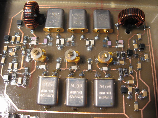
Two noise filters have been implemented that can be selected by means of I2C control in order to obtain the optimum situation for both CW and SSB. No new technology is needed for the noise filters. The filter switching method is identical to the one used on the Selectivity Board with pairs of FSA3157 SPDT bus switches. The CW noise filter is the same 3-pole 500Hz ladder filter design as is used in between hybrids in the CW roofing filter on the Frontend Board. The SSB noise filter is a 3-pole filter, quite similar to the hybridized 4-pole filters used in the SSB roofing filter. The picture below shows a close-up of the noise filter section on the Detector Board.
SSB Filter
The low IMD 9MHz QT crystals used in the frontends roofing filters are also used in the noise filters. At this position in the signal chain we are well protected for strong out of band signals. Out of band IMD is not an issue, however in-channel IMD is still important. The -17dBm output signal level of the Variable Gain Board is significant, so highly linear quartz is needed.
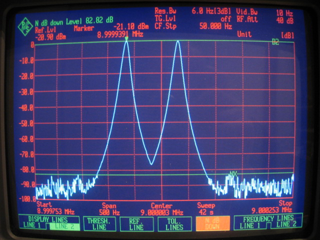
The following picture shows the 100Hz spaced IMD3 seen at the output of the SSB noise filter. The filter is measured together with the FSA3157 switches and the combined input power of the 2-tones is -17dBm. The resulting IMD if any is in the -90dBc noise floor well below the roughly -60dBc IMD levels of the Variable Gain Board. This is a good result given that two small compromises were taken. First the FSA3157 switches are powered with the nominal 5V instead of 7V and second, NP0/C0G grade MLCC's are used instead of the expensive ATC-B chip capacitors. Still the result is good enough hands down!
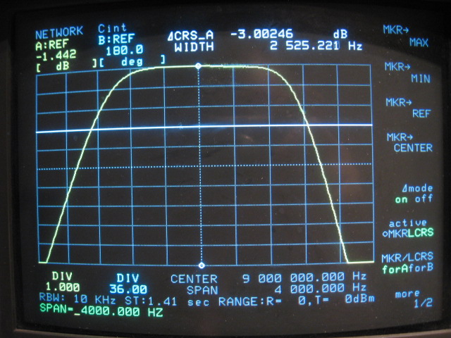
The following picture shows the pass-band of the SSB noise filter in a 4KHz wide sweep at 1dB per division. The -3dB bandwidth comes out at 2525Hz and the insertion loss equals -1.44dB. This is including the switching. The total insertion loss of the 3-pole filter is a little higher than that of the 4-pole roofing filter. This is due to the additional 0.80dB losses introduced by the FSA3157 bus switches.
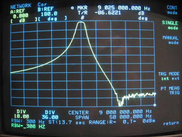
Although not very important in the role as a noise filter, the next picture shows a 50KHz wide sweep to inspect the stop-band performance of the filter. Compared to the 4-pole roofing filter the 3-pole noise filter is providing noticeably less selectivity and stop-band. Especially at the low frequency side where the effect of parallel resonance of the crystals is absent!
CW Filter
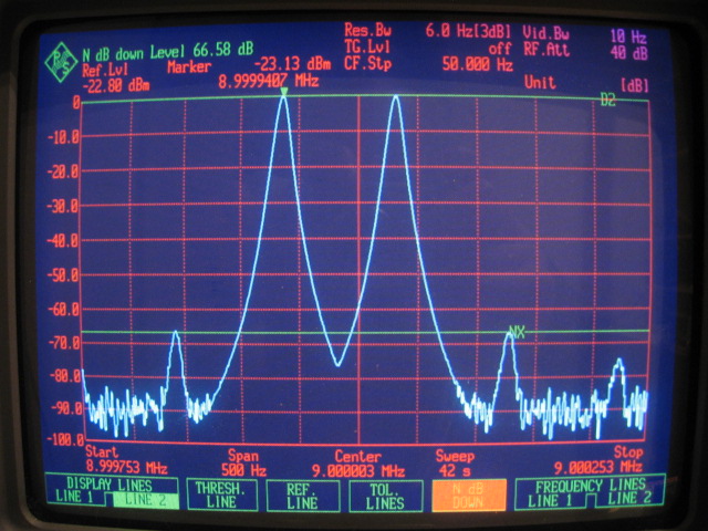
The same set of measurements is executed on the CW noise filter. This filter is identical to the 3-pole ladder filter used in the CW roofing filter. We already know that in-band IMD gets worse when the filter bandwidth is decreased. The following picture shows the 100Hz spaced IMD3 seen at the output of the CW noise filter. The filter is measured together with the FSA3157 switches and the combined input power of the 2-tones is -17dBm. Although now quite noticeable at almost -67dBc, the in-channel IMD is still well below the IMD produced by the Variable Gain Board.
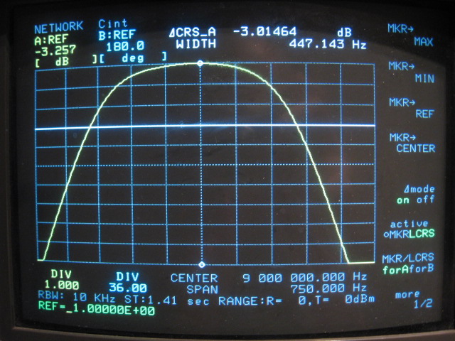
The following picture shows the pass-band of the CW noise filter in a 750Hz wide sweep at 1dB per division. The -3dB bandwidth comes out at 447Hz and the insertion loss equals -3.26dB. This is including the switching. The total insertion loss of the CW noise filter is higher than that of the CW roofing filter. This is the contribution of the FSA3157 bus switches.
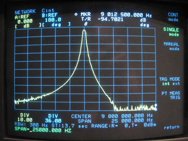
We conclude the slide show for the CW filter with the wide band 25KHz sweep to inspect the stop-band. The results are identical to what is obtained with the CW roofing filter.
Conclusion
Given the IMD performance of the noise filters obtained with QT quartz, both the SSB and CW filters are not bottlenecking the in-channel IMD of the receiver. They have been introduced to gain a small improvement with respect to the receivers NF by blocking the IF image noise and limiting the in-channel noise bandwidth to what is needed. This could also have been achieved with the QSD's I-Q outputs and additional signal processing in the baseband. The conventional IF filtering approach however turns out to be quite effective and easy too.
Please follow the links below to read more about the Detector Board.
Noise Filters
Quadrature Sampling Detector
Back to Detector Board
Back to the TOC
|